Continue to Site

Welcome to EDAboard.com

Welcome to our site! EDAboard.com is an international Electronics Discussion Forum focused on EDA software, circuits, schematics, books, theory, papers, asic, pld, 8051, DSP, Network, RF, Analog Design, PCB, Service Manuals... and a whole lot more! To participate you need to register. Registration is free. Click here to register now.

problems of setting circle pads

Status
Not open for further replies.

dum311

Junior Member level 1
Joined
Sep 11, 2007
Messages
18
Helped
0
Reputation
0
Reaction score
0
Trophy points
1,281
Activity points
1,444
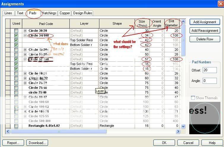
i am using CADSTAR software to design the impedance matching transformer IFT component
as shown in the link below:

ift2.jpg


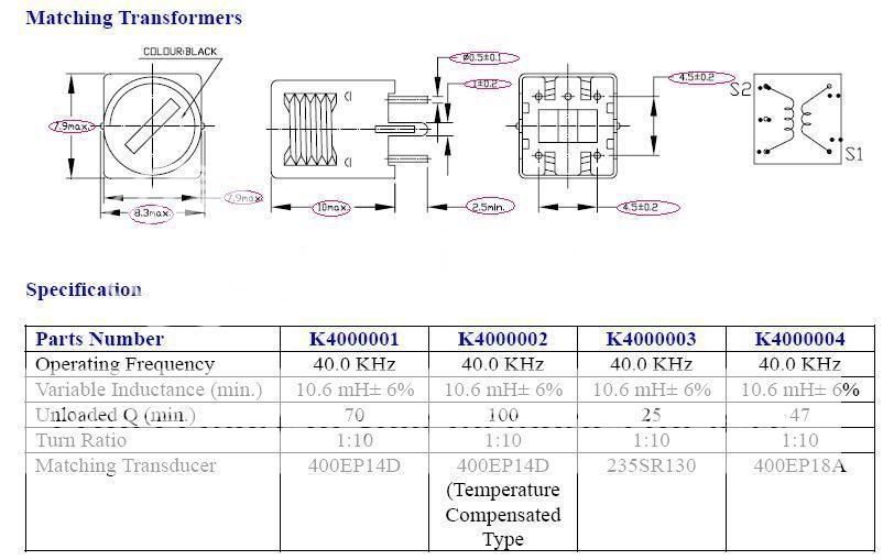
i am not very sure about the dimensioning of the circle pads
this is the link:

rt-1.jpg


if possible,do you have the symbol part and component part of this impedance matching transformer IFT?

i am looking forward to your replies as soon as possible.
thank you very much:D
 

i had modified the subject title of it and posted it again.

Added after 3 minutes:

by the way,i set the units on the settings menu to be thou.i multiple the dimensions with 39.37 and i added 10 because i afraid the hole will be too small.
 

Drill size is the actual hole will be digged in the PCB, and we need plated annular ring which is the pad size.
 

D

i multiple the dimensions with 39.37 and i added 10 because i afraid the hole will be too small.
The dimensions should be multipled by .03937.
The part has 5 round leads and 2 tabs to be slots.
Round leads are .024 DIA, Drill .035 DIA plated through
Slots .035 DIA X .047 plated through.

Don't forget to add Annular Ring to the hole sizes.

Mack
PCB Layout Blog
 

Status
Not open for further replies.

Part and Inventory Search

Welcome to EDABoard.com

Sponsor

Back
Top