Continue to Site

Welcome to EDAboard.com

Welcome to our site! EDAboard.com is an international Electronics Discussion Forum focused on EDA software, circuits, schematics, books, theory, papers, asic, pld, 8051, DSP, Network, RF, Analog Design, PCB, Service Manuals... and a whole lot more! To participate you need to register. Registration is free. Click here to register now.

problem with touch key using ttp223

Status
Not open for further replies.

ultrasonic.1991

Member level 3
Joined
Nov 6, 2015
Messages
60
Helped
0
Reputation
0
Reaction score
0
Trophy points
6
Activity points
554
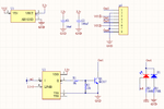
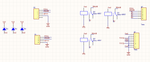
hi i designed a simple 4 pole touch key using ttp223 IC. i encountered a problem when using it. sometimes when i touch a key, another random key switches. and sometimes when i reset power, a key switches to a condition and never switches back after touching. i attached the 1 pole circuit and the power circuit. about the component with the picture of LED i should say that its a pcb pad connected to two back to back leds and a light guide which distributes light is placed over the leds. and a 4 mm glass is placed over the light guide. in the power circuit i used a 220 to 5v small smps.
what do you think the problem is?.
i found that there is something called snubber circuit which is a reisistor series with a capacitor parrallel with the contact pins of relay for suppressing exessive noise and also there is an option of optocoupler for isolation and suppressing noise. are these useful in my case ?
thanks in advance
 

Attachments

  • 2222.png
    2222.png
    24.1 KB · Views: 258
  • ggghhh.png
    ggghhh.png
    22.1 KB · Views: 140

I'm not surprised you have problems. Start by wiring a diode across the relay coils, cathode to VCC. Also connect a capacitor (about 10uF) between VCC and ground.

Brian.
 

Hi,

Start by wiring a diode across the relay coils, cathode to VCC.

to me it seems this has already been done by D1, D2 and D3. But to be hornest, this isn't obvious on the first sight.

BR
--- Updated ---

I made a quick web seach regarding the TTP223. It seems there a different versions available. Which one are you using? Im interested in the setting of the output pin (Q) functionality, which can be set by (I assume) LPMB.

BR
 
Last edited:

Hi,


to me it seems this has already been done by D1, D2 and D3. But to be hornest, this isn't obvious on the first sight.

BR
--- Updated ---

I made a quick web seach regarding the TTP223. It seems there a different versions available. Which one are you using? Im interested in the setting of the output pin (Q) functionality, which can be set by (I assume) LPMB.

BR
i used toggle mode and power on state=0 it's in the datasheet of ttp223 and I should correct my previous statement. the PCB pad is connected to the third pin of ttp223 and the LEDs are placed under the PCB pad.
 

Please provide a link to the used TTP223 vversion.
 

Hi,

the component shown in your circuitry do not match with the package pin-out shown in the datasheet i.e. pin 4 seems to be Vss in your schematic but it should be AHLB. I would agree with your statment "using toggle mode" IF pin 4 would be connected to Vss, but it is not, thus this pin is floating and its state is undefined. Pin 4 is named VSS, but I do not see an actual connection with pin 2, which is the IC's VSS pin. Connect pin 4 to VSS by means of an electrical connection (a wire).

BR
i agree with your point about pin4 being float but i don't think its the problem here because i saw another design that pin 4 was connected to vdd and had the same problem i think it has something to do with the power circuit.
 

Connect pin 4 to Vss, test it and we have a further look.
 

Status
Not open for further replies.

Similar threads

Part and Inventory Search

Welcome to EDABoard.com

Sponsor

Back
Top