Continue to Site

Welcome to EDAboard.com

Welcome to our site! EDAboard.com is an international Electronics Discussion Forum focused on EDA software, circuits, schematics, books, theory, papers, asic, pld, 8051, DSP, Network, RF, Analog Design, PCB, Service Manuals... and a whole lot more! To participate you need to register. Registration is free. Click here to register now.

problem with toggle switching in 555

Status
Not open for further replies.

rajaram04

Advanced Member level 3
Joined
Jun 17, 2012
Messages
871
Helped
6
Reputation
12
Reaction score
5
Trophy points
1,298
Location
earth
Activity points
7,687
Hello sir
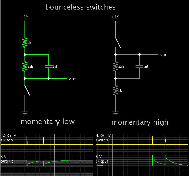
I designed a toggle switch based on the diagram shown below

url.gif


in the switching area it needs a micro switch or some mechanical design , no other electronic arrangment is working there or say not giving desired results

i used photodiode etc etc etc but same problem

how to sort it out ???????????????
 

Here is a website with abundant 555 IC ideas:

**broken link removed**

Are you making a bounceless switch? Consider these simple methods:


You can use a flip flop ckt.

Here you can go for a two transistor flip flop. This can support your power needs to.

It would be easy for me to help you if you mention what kind of circuit you are driving using this switch.
 

You can use a flip flop ckt.

Here you can go for a two transistor flip flop. This can support your power needs to.

It would be easy for me to help you if you mention what kind of circuit you are driving using this switch.


hmm sir i designed exactly what i uploaded the picture & using a micro switch for the purpose , i dont want 2 switched , so i made it , but wen i conneced a photodiode it simply switches it on but not able to switch it off or happen vice-verca depending on previous sate

- - - Updated - - -

Here is a website with abundant 555 IC ideas:

**broken link removed**

Are you making a bounceless switch? Consider these simple methods:


na na its not like that sir , its simply a toggle switch as we do in a power on/off mechanical switch for a cd player etc . .
just what i want to make is an electronics function in place of mechanical systems
 

hmm sir i designed exactly what i uploaded the picture & using a micro switch for the purpose , i dont want 2 switched , so i made it , but wen i conneced a photodiode it simply switches it on but not able to switch it off or happen vice-verca depending on previous sate

Since you mention a photodiode, this may be what you are looking for.
The toggle action is based on a flip-flop (as referred to in post #3), operating as a divide-by-two counter.


The action is similar to a push-on push-off switch.

I have not seen a schematic for making a 555 do the same thing.
 

Since you mention a photodiode, this may be what you are looking for.
The toggle action is based on a flip-flop (as referred to in post #3), operating as a divide-by-two counter.


The action is similar to a push-on push-off switch.

I have not seen a schematic for making a 555 do the same thing.


thanks sir but which oamp we can use in the above diagram u shown here ? 741 is okk or anythng alse ?
 

thanks sir but which oamp we can use in the above diagram u shown here ? 741 is okk or anythng alse ?

A 741 will need a bipolar supply to make the output go to zero. The flip flop input needs either 0V or supply V in order to trigger.

However there are other op amps which will go to zero, yet require only a single supply. Example, LM324.
 

kk sir nice to know about it :) , so any proper diagram relating lm324 ?
 

so any proper diagram relating lm324 ?

This is a simple setup for op amps, which is useful to demonstrate their behavior.

One important rule: No input pin should receive a volt level which is outside the volt range on the supply pins .
 

kk got it , i am using a photodiode at input via directly or via a simple transistor & using minimum voltage range of 3 volts & maximum of 9 volts as supply voltage , so i guess the input will not over ride the supply voltage ???

- - - Updated - - -

kk sir though its having a simple setup but i am not getting a proper diagram for it
 

Status
Not open for further replies.

Part and Inventory Search

Welcome to EDABoard.com

Sponsor

Back
Top