Continue to Site

Welcome to EDAboard.com

Welcome to our site! EDAboard.com is an international Electronics Discussion Forum focused on EDA software, circuits, schematics, books, theory, papers, asic, pld, 8051, DSP, Network, RF, Analog Design, PCB, Service Manuals... and a whole lot more! To participate you need to register. Registration is free. Click here to register now.

[SOLVED] Problem with three phase inverter when plugging IGBTs

Status
Not open for further replies.

khansaab21

Advanced Member level 4
Joined
Apr 12, 2008
Messages
108
Helped
4
Reputation
8
Reaction score
2
Trophy points
1,298
Activity points
2,214
Three phase inverter trouble

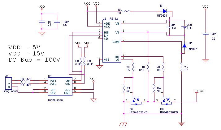
Following is the circuit of single phase of a three phase inverter.


I know I have been around with this circuit (with minor changes) before, but I couldn't help coming here back again with this as I couldn't get it to work. And this time, problem is very weird.

This inverter is working at its best when the DC bus voltage is 12V, output is on DC motors and output frequency is in the range of 0.1-0.5Hz.

But when DC bus voltage = 100 V, a weird thing starts to occur.

Plugging in IGBT's of first phase, every thing stays normal. Plugging in IGBt's of second phase DC bus voltage (being checked directly on the DC bus voltage input connectors) drops to about -500V and varies between -300 to -500V
Plugging in IGBT's of third phase the voltage stabilizes to -300V.

Obviously I cant connect load in this situation. During testings, I have even fried 2 gate drivers and a 4 IGBT's. I need to submit this project early next week. Please, I am in a dire need of help. How to fix this??
 

Re: Three phase inverter

if you are using IR's PSPICE model for the gate drive there is something wrong with it. i tried that in the past and found the error. had to open up their model and fix it. i forget what i did now, but i'm sure if i were looking at it again i could spot the problem.

not sure if this is your problem or not.. just reminded me of that experience.

Mr.Cool
 

Re: Three phase inverter

Mr. Cool, This is not just a simulation, as I have mentioned earlier, "During testings, I have even fried 2 gate drivers and a 4 IGBT's". All of this has occurred during the hardware development stage. This problem is really driving me crazy.
 

The problem can't be understood from the information you gave. Generally, as long as IGBTs are in place, the bus voltage can't become negative, because the reverse diodes are preventing it. Even a damaged IGBT would most likely fail short circuit, so this can't rarely happen. Also the rectifier supplying the DC bus would prevent voltage reversal. Something seems to be really odd with your circuit wiring or your measuring equipment.

P.S.: The ground scheme in your circuit is unclear. You have three different ground symbols, but it can't be determined, if and where the control and power ground are connected. If they are isolated, catastrophic failure of the circuit should be expected...
 

Yes, the supply is going negative, and I have checked it almost 20-30 times. The IGBt's are good shape as whenever I test them on 12V, everything (literally everything) runs fine, but this weird phenomenon occurs at 100V. As far as measuring equipment is concerned, it is a cheap multimeter (made in China) but I have been using it since the beginning of my engineering and it has got me through alot of projects.

I will recheck the wiring once again.

Following is the description of grounding scheme. Please tell me if there is something wrong with this.


And I have NOT connected the the 'Logic supply ground' and 'Low side supply ground' anywhere. Should they be connected together ??
 

According to the datasheet, IR2112 can accepts an offset up +/- 5V between VSS and COM. The separate grounds are mainly provided to improve the tolerance against interferences on the power ground in my opinion. But if you use a floating supply for VDD, you can't guarantee to keep the 5V limit. In my designs, I always connected both grounds on the driver board.
 

I connected the logic ground and low side ground with a 10 ohm resistor in between. Even then, this problem doesnt go away. Since, I have checked the IGBT's countless times, with multimeter and operationally on 12V, therefore, I think there is something wrong going with the DC Bus supply itself. Tomorrow I am gonna make a new supply and see if it solves the problem or not.

But before ending the post, I want to tell that inspite of taking -800V across their terminals many times (sometimes even longer than 5 min), the IGBT's are fully functional at 12V. Now, how can this be explained!!!
 

The situation is really bad guyz. I made a new 300V supply, connected a voltage divider across the output. Following is its circuit.


I took the output of 100V and still the voltage is going negative upto -900V. Then I connected the 300V output (Since IGBT's are rated for 600V), there was a spark and IGBT's were fried. Some new observations I made:

1. Plugging in IGBT's of phase 2 doesnt make the voltage negative, but connecting the firing commands of IR2112 to it, does.
2. Same thing goes for IGBT's of phase 3.
3. Phase 1 is working fine on its own i.e. IGBT's and firing commands input is making no mess at all and everything goes as expected.

Is it the voltage divider thats making the mess or something (unknown) is the culprit. Can somebody please help me with this.
 

The voltage divider can never work as a DC bus power supply. Also decoupling the DC bus with 10 uH is basically a wrong idea and involves a high risk of damaging the IGBT by inductive overvoltage, as long as no sufficient bypass capacitors (at least several 10 uF) are placed near the IGBTs.

But these point can't explain a negative voltage measured at the DC bus, for the reasons already said. There must be something you missed to tell, respectively you didn't yet see.
 

Ok, I have made some progress in the regard of the problem. Two consecutive sparks on the same point made me think that the maybe the power lines of DC bus are coupling on the IGBT board. I rearranged the wiring connections and placed a 100nF (400V) decoupling capacitor. Now the voltage is not going negative, but it stabilizes at around +8V - +12V, however, the DC bus volatage is +100V (ofcourse from the voltage divider, at the moment). The situation has gotten a little better, but

1. Will the voltage divider based DC bus wont work in the presence on no load on IGBT's (i.e. their output is open circuit, they are just switching at 20kHz)
2. How to achieve rated bus voltage at the IGBT's (maybe an issue of decoupling, capacitor size or something related)??

P.S. The inductor from the power supply have been removed, but the output is still being taken from the between the voltage divider (of course, for testing purposes and IGBT's arent sourcing/sinking to/from any output.)
 

Of course, it's a good idea to use reduced voltage and a current limited supply for first tests. But a resistor divider has too high impedance. A regular lab supply (e.g. 30 V) would be better.

1. IGBT bridges switching at no load will still draw some current due to switching losses.
2. Low inductance bypass capacitors at the DC bus near to IGBTs are essential for safe operation of IGBT bridges. Otherwise there is a risk of generating overvoltages that can become dangerous to the IGBTs, particularly when higher currents are switched, most likely not in a no load situation.

I don't know what happened to your circuit before. I already mentioned the potentially dangerous nature of the LC circuit, but also false gate control signals, causing a bridge short may have occured. Cautious designers are often placing a locking circuit before the gate driver, preventing simultaneous on-signals in hardware. It may be also a case of previously damaged IGBTs that showed catastropic failure stressed by some current.
 

Ok, I ll try to get my hands on the lab power supply but these days I am not going to the university as a couple of weeks earlier, I had an ankle surgery and cant really move around too much.

Basically I, the controller in this case dsPIC30F3010, and I am using its module which has a built in dead time generator. I have programmed the dead time to 3 uS, and I suppose, its more than enough for the components used.

But, I wanted to know that isnt a 470uF capacitor good enough to decouple the power lines, as still the real bus voltage cant be seen at the input power terminals of IGBT board. Is it due to the high impedence of resistor network??
 

the deadtime is a function of the maximum VARIATION of propegation delay from the controller chip to the IGBT. main contributors are the opto isolator, gate drive chip, IGBT delay times. 3uS may or may not be enough. try doubling that for now. you will know if it is enough if you are measuring the current in the leg and see a suddent spike.

Mr.Cooln
 

The problem has been solved. All mess was due to some bad/malfunctioning igbt's. Replacing them made the drive work. And even this source of error was discovered accidentally when a igbt blew up (I dont know why) and had to be replaced. That made the bus volatge rise to a significant level. Changing others made the the problem solve. Thank you all for providing me with your guidance. Now the problem lies with communication bus.
But I guess, the new problem has to be posted in the digital communication forum. Thanks once again for bearing me.
 

Status
Not open for further replies.

Part and Inventory Search

Welcome to EDABoard.com

Sponsor

Back
Top