Continue to Site

Welcome to EDAboard.com

Welcome to our site! EDAboard.com is an international Electronics Discussion Forum focused on EDA software, circuits, schematics, books, theory, papers, asic, pld, 8051, DSP, Network, RF, Analog Design, PCB, Service Manuals... and a whole lot more! To participate you need to register. Registration is free. Click here to register now.

Problem with the simulation of MULT18X18 in modelsim

Status
Not open for further replies.

usamaaslam1

Newbie level 6
Joined
Aug 21, 2009
Messages
11
Helped
0
Reputation
0
Reaction score
0
Trophy points
1,281
Activity points
1,355
hi

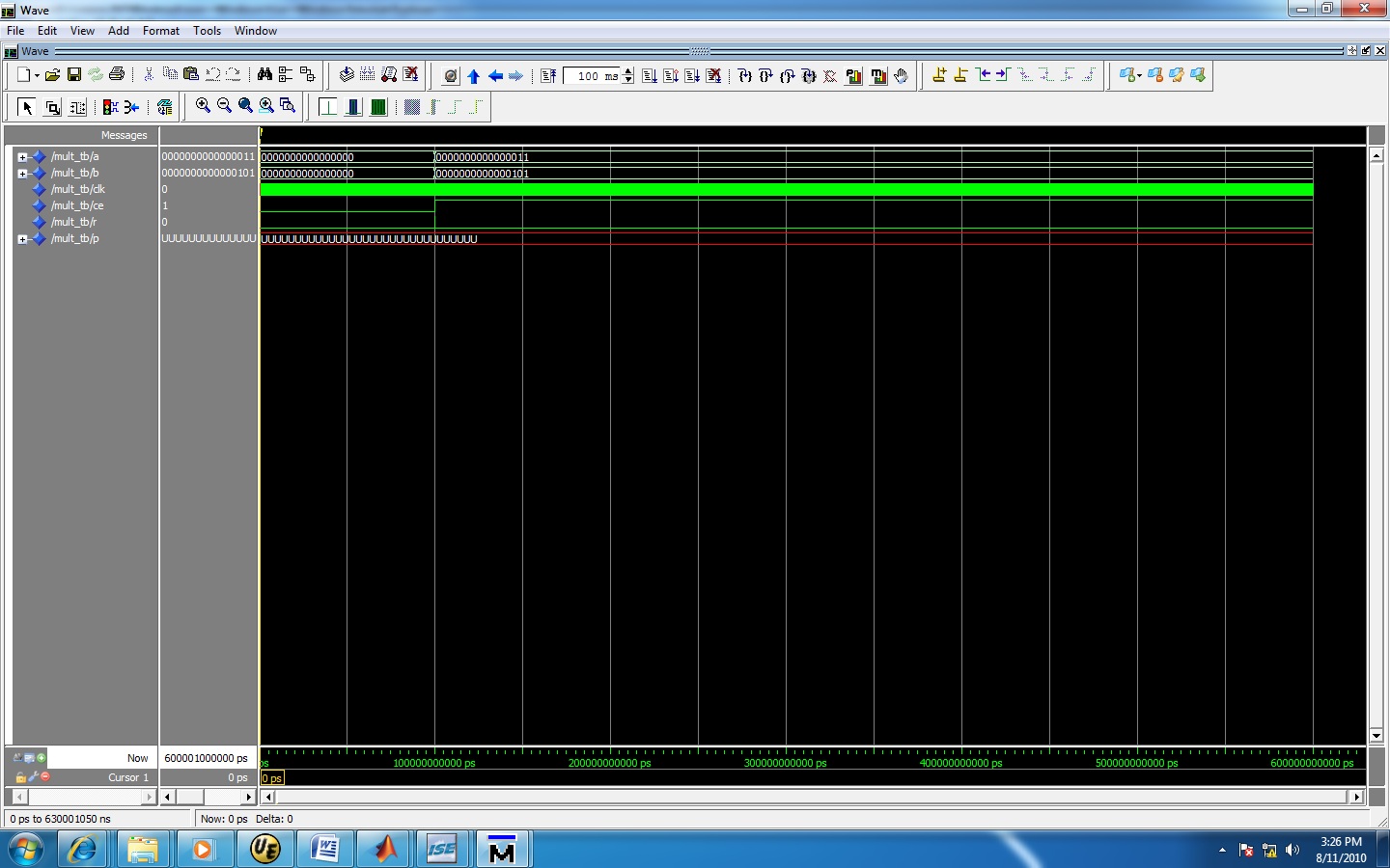
i have written a code to run the multiplier MULT18X18 placed in the libraries of virtex 2. When i simulate the multiplier in modelsim i dont the output. there is always an unknown value shown at the output. i have generated a 1 us clock in the test bench. when synthsized there is a warning that appears at that time "The block MULT18x18 is a black box."

what could be the problem with my design? what r the things i need to check to get my desired output?

Regards
Usama
 

The block MULT18x18 is a black box - This warning should be fine I think.
Can you post your code here.
Have initialized any temporary variables used to zero?

--vipin
https://vhdlguru.blogspot.com/
 

Here is the testbench that i have written

Code:
LIBRARY ieee;
USE ieee.std_logic_1164.ALL;
USE ieee.std_logic_unsigned.all;
USE ieee.numeric_std.ALL;
 
ENTITY mult_tb IS
END mult_tb;
 
ARCHITECTURE behavior OF mult_tb IS 
 
    -- Component Declaration for the Unit Under Test (UUT)
 
    COMPONENT MULT18X18
    PORT(
         A : IN  std_logic_vector(15 downto 0);
         B : IN  std_logic_vector(15 downto 0);
         C : IN  std_logic;
         CE : IN  std_logic;
         R : IN  std_logic;
         P : OUT  std_logic_vector(31 downto 0)
        );
    END COMPONENT;

   --Inputs
   signal A : std_logic_vector(15 downto 0) := (others => '0');
   signal B : std_logic_vector(15 downto 0) := (others => '0');
   signal clk : std_logic := '0';
   signal CE : std_logic := '0';
   signal R : std_logic := '0';

 	--Outputs
   signal P : std_logic_vector(31 downto 0);

   -- Clock period definitions
   constant clk_period : time := 1us;
 
BEGIN
 
	-- Instantiate the Unit Under Test (UUT)
   MULT18X18S_inst : MULT18X18
   port map (
      P => P,    -- 36-bit multiplier output
      A => A,    -- 18-bit multiplier input
      B => B,    -- 18-bit multiplier input
      C => clk,    -- Clock input
      CE => CE,  -- Clock enable input
      R => R     -- Synchronous reset input
   );

   -- Clock process definitions
   clk_process :process
   begin
		clk <= '0';
		wait for clk_period/2;
		clk <= '1';
		wait for clk_period/2;
   end process;
 

   -- Stimulus process
   stim_proc: process
   begin		
      -- hold reset state for 100ms.
      wait for 100ms;	

      wait for clk_period*10;
		 R <= '1';
		 CE <= '0';
		wait for clk_period*5;
		 R <= '0';
		 A <= "0000000000000011";
		 B <= "0000000000000101";
		wait for clk_period*2;
		 CE <= '1';
      wait;
   end process;

END;
 

What is the output you are getting when you simulate this. Make sure that you simulate for enough time(may be 110 ms).
 

here is the simulation results of the code


I dont know why it shouldnt work. Can you post your UUT code here.
 

is it possible you want the "library unisim" "use unisim.vcomponents.all" added to the library declarations? modelsim will still need to be set up correctly to find things like simprims.
 

Status
Not open for further replies.

Part and Inventory Search

Welcome to EDABoard.com

Sponsor

Back
Top