Continue to Site

Welcome to EDAboard.com

Welcome to our site! EDAboard.com is an international Electronics Discussion Forum focused on EDA software, circuits, schematics, books, theory, papers, asic, pld, 8051, DSP, Network, RF, Analog Design, PCB, Service Manuals... and a whole lot more! To participate you need to register. Registration is free. Click here to register now.

[SOLVED] Problem with Switch / Coin Slot Signal

Status
Not open for further replies.

corpuralx

Junior Member level 3
Joined
Oct 12, 2013
Messages
26
Helped
0
Reputation
0
Reaction score
0
Trophy points
1
Activity points
253
The basics of the basics. We're doing a project using only basic gates (some advance ones), I already made a circuit on proteus, simulated it, and everything's fine.

[PHASE1]

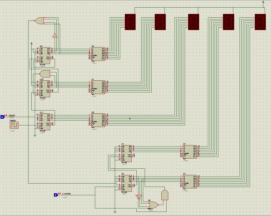
The logic of our project, a five minutes count down timer with (2) 7-segment display counter that comes with a switch [which will be our COIN SLOT]. The time the source is plugged in, the countdown timer starts and the counter is automatically sets to 01. Each time the countdown timer reach 0:00 and restarts to 5:00, the counter increases by 1s, so after after 01, it turns 02, then 03 and vice versa till it reach 99. For the switch[logicstate in proteus], each time it is pressed, the counter is reduced by 1s, e.g 04 to 03 then 02.

The countdown timer is made using a 555 timer, 3 counter ic 74LS192 and 3 bcd decoder 74LS47, with conditions to make it 5:00 mins. The 1st 74LS192 ic that hold the minute display, has a condition that once it reach 5, it ups the counter by 1s.

The counter is made using 2 counter ic 74LS192 and 2 bcd decoder 74LS47, with condition [for the down switch], each time the "oneths" segment reaches 9, it will down the "tenths" segment by 1 [E.G. 10 -> 09], this only occurs during the down switch is pressed. However, by means of the timer (not by the switch), it will not down the "tenths" segment.

[THE PROBLEM]

Now, the breadboard part, the down switch I used was a microswitch, connected to a debouncer, [https://3.bp.blogspot.com/_vh8XDhY5...AAABA/8tIEO7LV4A4/s1600/switch+debouncer.BMP]. I observed that the switch, even it is not pressed, it generates a small signal/a small voltage, which contradict/conflict with the condition I made in the counter section part. So meaning, it is always on, even its just 0. Which at proteus, we're only using LOGICSTATE so its only 0 or 1, so what happens, the condition which occurs only when the switch is pressed also works on the timer. After the 08 display, its supposed to dispaly 09, but instead displays 99. It means it down the tenths segment due to the debouncer, i replace the switch and debouncer with a coin slot and they are just the same.

I tried other debouncers, that doesn't have the same concept with the first, but the circuit does not work, counter doesn't work as well. Any suggestions? Ideas what to do?

[PHASE2]

Due to the problem, I decided to remove the other segment on the counter section so it would only count 1 to 9. I then replaced the microswitch with a coin slot, the next problem is, Instead it count down by 1, each time i insert a coin, the counter downs the counter by either 2s, e.g. 8->6 or 3->1. It means, that the microswitch 1st debouncer as well as the coin slot has the same concept, which has small signal or voltage even it is idle. Any suggestions?

Is there any methods how to supress the small signal into 0 [no voltage] which comes from the coin slot? any working debouncers? Thanks
 

Possibly some race condition occurs in the practical circuit of debounce. Try adding a small cap, say 1nF - 10nF range from each of your 10K to Gnd.
 

Possibly some race condition occurs in the practical circuit of debounce. Try adding a small cap, say 1nF - 10nF range from each of your 10K to Gnd.

On my breadboard, i actually used 1k resistor instead of 10k resistors, since I only have 6V source. I'll try adding a cap ranging either 10uf - 20uf would that be possible? Thanks

Aside from that, any idea what circuit(any other debouncers/circuit) had to add, so that the counter would only down once? 4-3-2? not by twos 8-6-4-2? or random #s. Thanks

That is interesting.
While your 555 will tolerate the 6v supply, it is likely that your TTL gates will misbehave/ burnout with the 6v, since the MAX Vcc for ttl is 5.5v.

Also your reason to use 1K instead of 10K is not clear. And why would you place 10u - 20uF when I recommended 1n - 10nF ?
Where else have you made such arbitrary substitutions ......
 

Is there any methods how to suppress the small signal into 0 [no voltage] which comes from the coin slot? any working debouncers? Thanks

Hi you need not to write this much, I still doesn't get anything.. you can post your Proteus file, and your voltages used in hardware..
 

That is interesting.
While your 555 will tolerate the 6v supply, it is likely that your TTL gates will misbehave/ burnout with the 6v, since the MAX Vcc for ttl is 5.5v.

Also your reason to use 1K instead of 10K is not clear. And why would you place 10u - 20uF when I recommended 1n - 10nF ?
Where else have you made such arbitrary substitutions ......

Sorry, still a newbie when it comes to this thing. I adjusted my source to 4.5V and replaced the 1k resistor into 10k resistors. There are times, the whole circuit freezes and continues. I still had to purchase 1nf & 10nf capacitors since I only had 4.7uf, 10uf, 22uf, 33uf, 47uf, 50uf and 100uf. I don't have 0.01uf which i believed equals 10nf capacitor reqd. ANy other advice?

Hi you need not to write this much, I still doesn't get anything.. you can post your Proteus file, and your voltages used in hardware..

The circuit on proteus everything works fine, since I only used LOGICSTATE as switches, however on breadboard, I used a microswitch with a debouncer, which doesn't work, same for a tact switch alone.
 

Hi i asked to know the operation of your project, so post your Proteus file or a schematic of it... To check a counter easily,
1, remove the debounce circuitry
2 ground the clock input with a 10 k pull down resistor
3,now give the pulses by connecting the wire on Vcc now check the operation and fix the problem on debounce circuit..
after that fixing debounce circuit is easy...
 
Here's the screenshot of our circuit in proteus.
 

As a general good practise in digital circuits, ALL unused inputs should be either grounded or pulled up.
In the absence of such, there is a high possibility of incorrect functioning.

I notice that there are several places where such inputs have been left open/ floating.
Since you have already gone to great lengths to have proper debounce, then THIS might be the other cause of your troubles.
 
Did you checked it without debounce circuit??

yeah, and it give me random #'s.

As a general good practise in digital circuits, ALL unused inputs should be either grounded or pulled up.
In the absence of such, there is a high possibility of incorrect functioning.

I notice that there are several places where such inputs have been left open/ floating.
Since you have already gone to great lengths to have proper debounce, then THIS might be the other cause of your troubles.

Thank you for the advice. I'll ground the inputs on the 3rd 74LS192 which are left hanging.

As general, instead of 00 - 99, we decided to make the counter only read 0 - 9, so we removed the 1st 7 segment, BCD-decoder, 74LS192 and the conditions made on the 2nd part of the counter section. The problem left for us now, is that, the circuit still count downs by "two's" instead of ones, each time we dropped a coin on the coin slot.

@kripacharya
I tried putting a pair of capacitors 1nf and 10nf on each resistors, but still doesn't work, pelase correct me if I'm wrong, I connected the other end of the capacitor on the ground, do I need to connect it in series with the resistor? or connect the other end iin VCC or GND?

Thanks for the help everyone.

- - - Updated - - -

Would it be possible for the circuit to work, if we used a relay switch? If not necessary, what other methods do you can advice? THanks very much

- - - Updated - - -

Another one, Im very sorry guys, but do you mean, when you say for example a resistor or capacitor, is either pulled up or down? what does it mean? Very sorry, still a newbie here.
 

https://en.wikipedia.org/wiki/Pull-up_resistor

It is to make sure the default input (when not giving any input) of a circuit to be a particular state so that avoids the unwanted mis-assumptions of circuit that It was a pulse and to count them correctly....
 
Oh, thanks for that information. I'm really stuck on amplifying the double signal/pulse that our coin slot gives.

Imagine an up/down counter circuit, wherein 2 micro switch with a debouncer is used, pressing would count up or down the two 7 segment display from 00 - 99, counting by ones ( 1 -> 2 -> 3). Now changing that microswitch with a coin slot, removing the connection output of the debouncer from the 74LS192 ic pin4 or pin5, then connecting the counter/clock of the coin slot to the 74LS192 pin4 or pin5. Each time a coin i inserted, the display will be (1 -> 3 -> 5).
By the way, my coin slot only has 3 wires, red(vcc), black(gnd) and white(the clock/pulse).
 

Hi what do you mean amplification or what do u mean double pulse??

you need to increment 2 pulses per count or you need one pulse but the coin slot gives you two pulses per coin???
 
I deleted this since Venkadesh_M pointed out in #16 & #18 that the illegal condition can't happen the way the switch is wired up in this application. The only thing that can cause unexplained multiple output pulses is if noise is present on the inputs or power supply pins.
 
Last edited:
Hi the SW1 and SW2 or not two different switches in OPs requirement and also the race condition occurred in your circuit is when both witches open so A and B high that is not going to happen with a single switch because the cant make contacts between both positions.... for the circuit shown It will race in 00 input and not in 11 input.....
 
Deleted in relation to post#15
 
Last edited:
for 1 and 1 inputs its not going to race that means for the lever in between two contacts it will remain in 1 1 or no change condition..
your simulation results look opposite....

- - - Updated - - -

The race condition will only occur in 0 0 input that means closing both switches which is impossible........
 
I think he needs to get a digital scope and see what is actually happening to cause the multiple pulses. From a theoretical point, it should not change states but when there is noise, for some reason, you can get undefined behavior. So using a storage scope and capture the input states and outputs is the fastest way to solve this problem.
 
Last edited:
It has been months since I went back hre. I appreciated everyones help. You have my thanks to each one you guys. Though, unfortunately, we were not able to pass the said course, but we're still aiming it to pass again. Hoping for everyones help for our next plates/exercises. Thanks.
 

Status
Not open for further replies.

Part and Inventory Search

Welcome to EDABoard.com

Sponsor

Back
Top