Continue to Site

Welcome to EDAboard.com

Welcome to our site! EDAboard.com is an international Electronics Discussion Forum focused on EDA software, circuits, schematics, books, theory, papers, asic, pld, 8051, DSP, Network, RF, Analog Design, PCB, Service Manuals... and a whole lot more! To participate you need to register. Registration is free. Click here to register now.

[SOLVED] Problem with RF module interfacing to PIC micro Controller

Status
Not open for further replies.

thunderboympm

Full Member level 5
Joined
Sep 17, 2007
Messages
243
Helped
32
Reputation
64
Reaction score
29
Trophy points
1,308
Location
Malappuram, India
Activity points
2,469
hai,
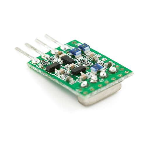
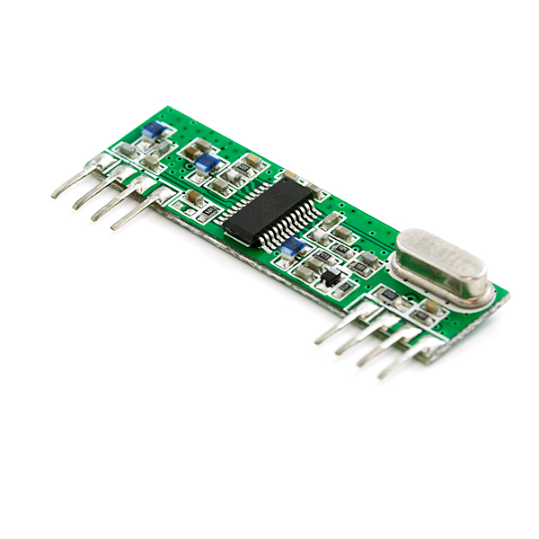
i got a problem with my RF module and PIC micro controller. i am creating a project for my friends with RF module, the transmission and reception of data is OK. the problem is when i am connecting the HT12D to my micro controller the pins voltage get dropped down. that is when i am connecting the PIC16F73 to HT12D's VT the voltage in the pin get dropped to 0.15 V. how can i connect the VT pin of HT12d to PIC's external Interrupt?
please help me. and thanks in advance.
 

Do You mean that it never goes higher than 0,15V?
Datasheet says: "The output of the VT pin is high only when the transmission is valid. Otherwise it is always low."


Yea,
i am using HT12E and HT12D. when i am connecting the encoder and decoder alone the working is OK, but when i am connecting the PIC micro controller the O/P voltage is dropping to 0.16V
 

i saw it. but it is not using encoder and decoder. the Manchester encoding is doing in this program.
 

Here are some other examples:

DIY remote control based on PIC

Controlling the Project with a Microcontroller
Using these RF transmitter & receiver circuits with a Microcontroller would be simple. We can simply replace the switches used for selecting data on the HT-12E with the output pins of the microcontroller. Also we can use another output pin to select TE, or transmit enable on the HT-12E. By taking pin-14 LOW we cause the transmitter section to transmit the data on pins 10-13.

To receive information simply hook up the HT-12D output pins to the microcontroller. The VT, or valid transmission pin of the HT-12D could signal the microcontroller to grab the 4-bits of data from the data output pins. If you are using a microcontroller with interrupt capabilities, use the VT pin to cause a jump to an interrupt vector and process the received data.

The HT-12D data output pins will LATCH and remain in this state until another valid transmission is received. NOTE: You will notice that in both schematics each of the Holtek chips have resistors attached to pins 15 and 16. These resistors must be the exact values shown in the schematic. These resistors set the internal oscillators of the HT-12E/HT-12D. It is recommended that you choose a 1% resistor for each of these resistors to ensure the correct circuit oscillation.

You will need a few pieces of 22 gauge wire for the antennas on the RE-99 and TX-99. Both units come with full instructions for selecting the length of wire to use for each antenna. For a quarter wave antenna you will need 9.36 inches of 22 gauge wire for both the transmitter and receiver boards.


Quoted from project below:


The project above mentions interfacing a PIC with the HT-12E/D, that is the closest reference I can find at the moment. I'll keep my eye out for additional info for you.
 
There are basically two explanations:
- the module isn't receiving anymore, after the PIC is connected, e.g. due to interferences or any wiring fault
- the PIC is programmed incorrcectly and driving the respective pins low
You should be able to distinguish between both, but it's hard to see it from a distance.
sir,
you are currect. i solved the VT Problem. but now another problem is i am using PORTA to the data of the RF module. when i am connecting the PIC the O/P voltage is dropping. even if the VT givings High voltage.
here is my circuit diagram
 

Attachments

  • HT12D and PIC.bmp
    1.4 MB · Views: 95
Last edited:

I've been looking over forum discussions concerning data transmission over the HT-12E/Ds and the throughput is horribly slow. You maybe much better off implementing Manchester Encoding via the PIC and just send/receive the data directly to the TX/RX pair.

Here's a discussion on Holtek's forum:

**broken link removed**

You'd be much better off implementing a soft encoding/decoding scheme, at least in my opinion.

---------- Post added at 10:24 ---------- Previous post was at 10:21 ----------

One of the postings in the Embedded Wireless Network Group has example code for a PIC/Manchester implementation.
 
Status
Not open for further replies.

Part and Inventory Search

Welcome to EDABoard.com

Sponsor

Back
Top