Johnny_YU
Member level 2
HI all
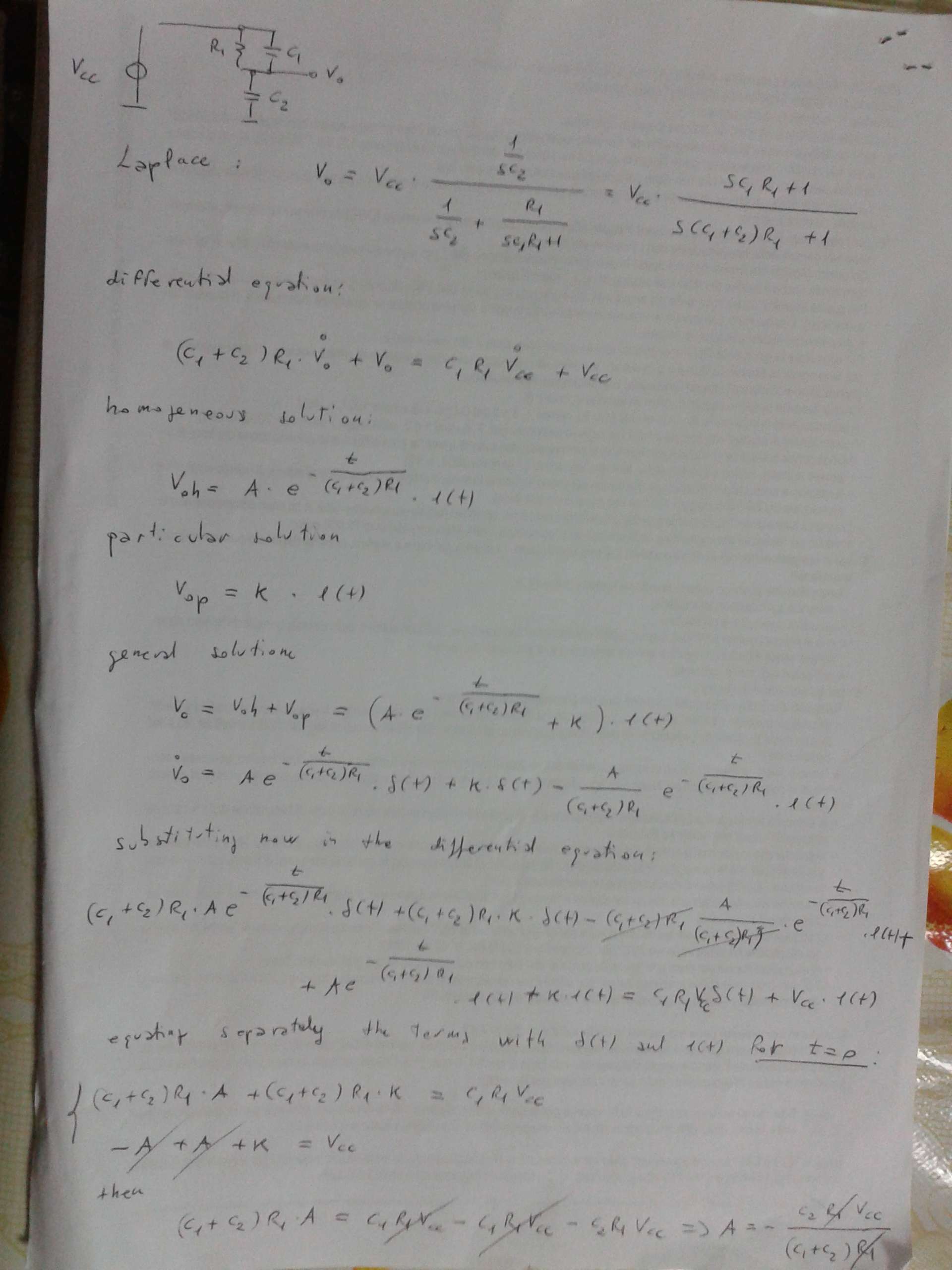
I'm trying to analyse a simple RC circuit.
Condition: the initial energy stored in this simple RC circuit is ZERO.
AT t=0s ,a DC voltage source of 5 Volts is applied to the circuit.
I need to find the Transient Response of Vd.
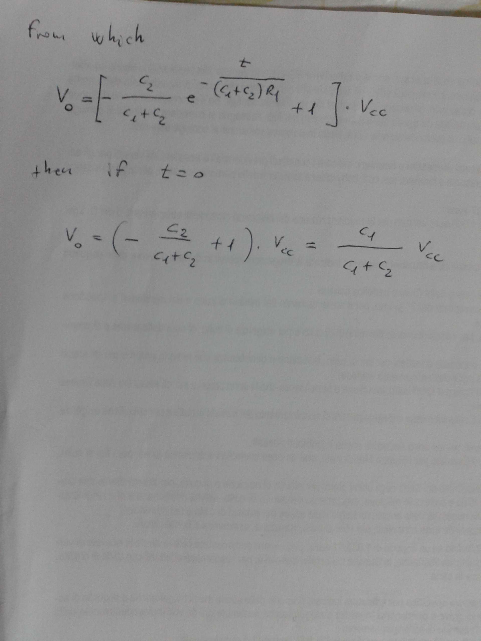
I did the calculations, the result indicates that when t=0s , Vd approaches to 5Volts.
And then I use 'Multisim 12' to do a Transient Response simulation for Vd, the result indicates that when t=0s, Vd approaches to 2.5Volts.
So, which One is Correct? Is there anything wrong with the Calculations or the Simulation?
Thanks!


I'm trying to analyse a simple RC circuit.
Condition: the initial energy stored in this simple RC circuit is ZERO.
AT t=0s ,a DC voltage source of 5 Volts is applied to the circuit.
I need to find the Transient Response of Vd.
I did the calculations, the result indicates that when t=0s , Vd approaches to 5Volts.
And then I use 'Multisim 12' to do a Transient Response simulation for Vd, the result indicates that when t=0s, Vd approaches to 2.5Volts.
So, which One is Correct? Is there anything wrong with the Calculations or the Simulation?
Thanks!