Continue to Site

Welcome to EDAboard.com

Welcome to our site! EDAboard.com is an international Electronics Discussion Forum focused on EDA software, circuits, schematics, books, theory, papers, asic, pld, 8051, DSP, Network, RF, Analog Design, PCB, Service Manuals... and a whole lot more! To participate you need to register. Registration is free. Click here to register now.

[SOLVED] Problem with my serial port code

Status
Not open for further replies.

Cheetos

Member level 3
Joined
May 26, 2011
Messages
57
Helped
1
Reputation
2
Reaction score
1
Trophy points
1,288
Activity points
1,700
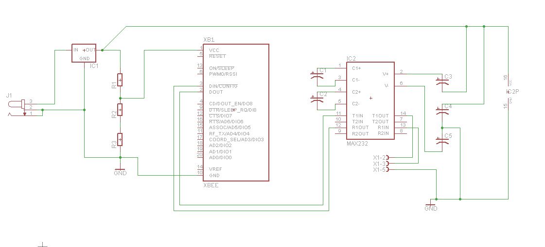
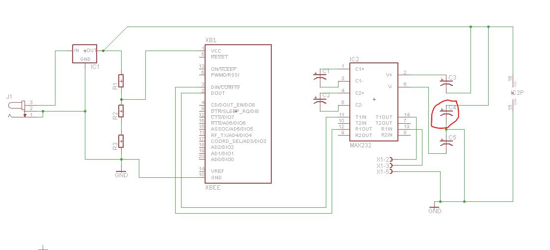
This is my code in my program. i am having problems because when i transmit '1', i receive a different character. sometimes it is even a special character. by the way my OS is LINUX, i am using USB to RS232 converter, Codeblocks with Libserial library, and Xbee modules. Please help :(


Code:
#include <iostream>

#include <fstream>

#include <SerialStream.h>

#include <cstdlib>
 
//#include <sys/types.h>

//     #include <sys/stat.h>

//    #include <fcntl.h>


using namespace std;

using namespace LibSerial;


main(){

double i;

char character;

SerialStream serialPort;

serialPort.Open("/dev/ttyUSB0");

serialPort.SetBaudRate( SerialStreamBuf::BAUD_9600) ;

serialPort.SetCharSize( SerialStreamBuf::CHAR_SIZE_8 ) ;

serialPort.SetNumOfStopBits(1) ;

serialPort.SetParity( SerialStreamBuf::PARITY_NONE ) ;

serialPort.SetFlowControl( SerialStreamBuf::FLOW_CONTROL_NONE ) ;


 if ( ! serialPort.good() )
    {
   
     std::cerr << "Error: Could not open serial port "
                 
	       << "/dev/ttyUSB0"
                 
	       << std::endl ;
        
                exit(1) ;

    }


while(i<20){


sleep(1);

serialPort<< '1' <<std::endl;
sleep(1);

//printf("i transmitted i think\n");
i++;


}


serialPort.Close();


return (0);

}
 
Last edited by a moderator:

Can you post or upload the schematic of your design?

Please tell me you are not connecting the output of your RS-232/USB converter directly to the XBee module.

How and at what level are you powering the XBees?

BigDog
 

I did not connect it directly, i connected them RS232 -> MAX232 -> then XBee module. i am powering my Xbees with 3.3 volts. In the schematic nevermind the three resistors, i replaced them with 3.3v Voltage regulator where in the input is connected to output of 5v regulator IC1(LM7805). my power source is Ac to DC adapter input 100~240V 0.4A output 9V DC 10W


<a href="http://obrazki.elektroda.pl/48_1317386954.jpg"><img src="http://obrazki.elektroda.pl/48_1317386954_thumb.jpg" alt="48_1317386954.jpg" /></a>
 

The V+ and V- capacitors are not connected properly.
There should be a capacitor from V+ to GND, V- to GND and sometimes a V+ to V- capacitor

Also MAX232 is not 3v3 compatible (I'm not sure what supply you use), there is a specific model for 3v3 which is MAX3232

Alex
 
I did not connect it directly, i connected them RS232 -> MAX232 -> then XBee module. i am powering my Xbees with 3.3 volts. In the schematic nevermind the three resistors, i replaced them with 3.3v Voltage regulator where in the input is connected to output of 5v regulator IC1(LM7805). my power source is Ac to DC adapter input 100~240V 0.4A output 9V DC 10W

Good. Your schematic looks correct. Are the XBees Series 1 or Series 2? Where are you receiving the transmitted '1' characters?

Also have you performed a loopback test on the RS-232/USB Converter using a LibSerial program as the testbed?

BigDog

---------- Post added at 14:04 ---------- Previous post was at 14:01 ----------

Good catch, Alex.
 

i got this schematic from the internet, i'll try your suggestion, thanks! :)

---------- Post added at 21:14 ---------- Previous post was at 21:10 ----------

Good. Your schematic looks correct. Are the XBees Series 1 or Series 2? Where are you receiving the transmitted '1' characters?

Also have you performed a loopback test on the RS-232/USB Converter using a LibSerial program as the testbed?

BigDog

---------- Post added at 14:04 ---------- Previous post was at 14:01 ----------

Good catch, Alex.

I am currently using Xbee Series 2. My code above is supposed to be transmitting '1'.

for the testing:
I ran the code above in a different PC
I connected my Xbee development kit to my laptop and used XCTU to know if it receives the correct character.
while the program is running, the characters i receive in XCTU is not '1'.
 

I have no idea where you saw that wrong schematic but the Internet is full of correct ones

In any case the most valid place to look is the datasheet https://www.ti.com/lit/ds/symlink/max232.pdf
page 7

or
page 17

Alex

---------- Post added at 16:20 ---------- Previous post was at 16:18 ----------

You didn't specify the supply level of MAX232.
Also if it is 5v make sure that the Xbee inputs are 5v compatible when you use 3v3 supply.

Alex
 
i followed this schematic from sodoityourself.com. my power source for my schematic is a 9 volt 10W AC to DC adapter, i used 5 volt regulator for MAX232 power supply and 3.3v regulator for Xbee power supply
66_1317388743.jpg


---------- Post added at 21:29 ---------- Previous post was at 21:26 ----------

by the way, i also tested my circuit in XCTU, i was able to transmit '1' to a microcontroller that i programmed. what could be the problem? :(
 

I am currently using Xbee Series 2.

Have you used the XCTU to properly configure the XBee Series 2s? The XBee Series 2s typically do not connect right out of the box. Perform a loopback test using the remote XBee without a RS-232 transceiver, just short the TX/RX lines of the remote XBee and while typing test characters into XCTU, you should see the characters echoed back.

However, you'll need to correct the RS-232 transceiver issue, for the XBee attached to the XCTU, as Alex stated before proceeding.

The XBee modules pins are 5V tolerant. Another options is to use a UART/USB Bridge Chip Breakout Board like the FTDI FT232R, they usually have a selected pin voltage level of either 5V or 3.3V and you would not need the RS-232 Transceivers. I usually use this setup to configure all the XBees in a project. The FT232R Breakout Boards come in handy for other projects as well.

BigDog
 

I have configured the Xbee Series 2s correctly. Also, all the tests were done. My max232 is supplied with 5 volts, my xbee is supplied with 3.3 volts. and i noticed that the capacitor(in red circle) is the one Sir Alex was talking about


Actually C3 is wrong, it is supposed to be connected from pin2 to GND.
C4 is currently connected between the output of the regulator output and the GND so it no problem at all

Alex
 

i have done all the corrections in the schematic, still it goes wrong :( . can the issue of this one is that the Driver is installed incorrectly? or i am using Ubuntu OS?
 

You could use a null modem cable and test the Serial Library by send ASCII characters directly from your Linux box to your laptop and vice versa .

BigDog
 

Thank you all for your help, the problem is now solved :) the issue is not about the hardware and the software, it's in my OS, we reformatted our PC an installed again my devices :)
 

Status
Not open for further replies.

Similar threads

Part and Inventory Search

Welcome to EDABoard.com

Sponsor

Back
Top