Continue to Site

Welcome to EDAboard.com

Welcome to our site! EDAboard.com is an international Electronics Discussion Forum focused on EDA software, circuits, schematics, books, theory, papers, asic, pld, 8051, DSP, Network, RF, Analog Design, PCB, Service Manuals... and a whole lot more! To participate you need to register. Registration is free. Click here to register now.

Problem with MOC3011 & BT136

Status
Not open for further replies.

rushi53

Member level 2
Joined
Aug 19, 2009
Messages
46
Helped
2
Reputation
4
Reaction score
1
Trophy points
1,288
Location
India
Activity points
1,632
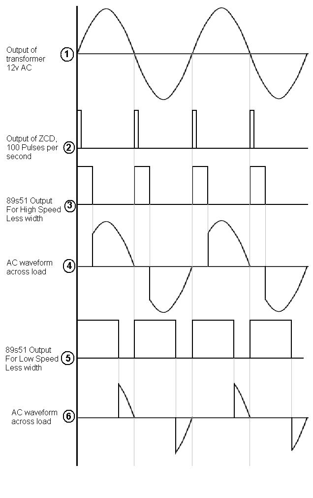
Hi, I am working on Temperature controlled fan. (or say, Fan Dimmer)
In this I have used 89s51, ZCD(using LM358), MOC3011 & BT136
Out of these, ZCD and 89s51 are working properly.

I require 0 to 10 steps for speed of fan.
When I set fan to zero speed, the fan is turned off, this is fine.

But when I set fan to speed = 1, fan is rotating with full speed (speed = 10)
so for variation between 1 to 10, fan is showing constant speed, which is wrong.

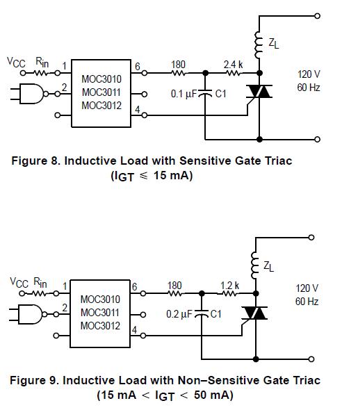
I am attaching the circuit of MOC3011 & BT136


Please help me finding the fault in the circuit. Or kindly suggest any replacement for this circuit.
 

This was the only fault i found out when assembled the same circuit. Its again the fault the source code. Nothing wrong with the hardware. Cheers
 

Hi pranam77, thanks for the quick reply...

As per my view, program is correct.

Microcontroller is able to generate PWM of 100Hz. Which is given to MOC3011 for firing of BT136

See the attached waveforms


These are expected waveforms.
Out of these, I have achieved 1, 2, 3 and 5
I am not able to get 4 and 6.

Correct me if my expected waveforms are wrong.
 

Your circuit misses the RC snubber that are required in the MOC30xx datasheet for inductive loads. Depending on the motor inductance, you have a high risc of retriggering the opto triac by the commutation dV/dt without a control signal. Use the suggested circuit and try again.
 

@FvM, thanks for the reply...

I have gone through datasheet of MOC3011 and found 2 circuits...

My Questions:
1. Are these circuits which you are referring? (snubber circuit)
2. Which of these 2 should I use? (figure 8 or figure 9

Here are those circuits:
0_1257514629.jpg


Waiting for your reply...
Thanks...
 

Yes, a circuit of this kind is necessary with inductive loads, sometimes even withs resistive loads (when large transients
are present in the mains voltage). According to the datasheet, BT136 is a sensitive triac. The RC dimensioning
isn't that critical in my opinion.
 

Try swapping the MT1 and MT2 pins. Some times these too have created problems with my HW. Cheers
 

I have tried with second snubber circuit
I used R=1.2k and C=0.22microF

Register burnt when I switched on power supply.
I used 1/4watt register (quarter watt) Is this the reason behind burning of register?
Should I use half watt or 1 watt register.

Also please tell me about capacitor rating. I have used 0.22microF/63volt capacitor.
what should be the voltage rating of capacitor?
 

i think the problem is not come from snubber, but the source code, i not sure using pwm is the best practice to trigger this circuit.

in my opinion you should calculated proportion delay since every zero crossing signal as starting point.
 

dian said:
i think the problem is not come from snubber, but the source code, i not sure using pwm is the best practice to trigger this circuit.
in my opinion you should calculated proportion delay since every zero crossing signal as starting point.
Yes i do agree with you Dian. Coz i had faced problem with the code of the same circuit as PWM cannot control AC. You need to control the phase angle to vary the brightness or the speed. Cheers
 

@pranam77
@dian

I am doing the same thing which u both are saying.
I am generating delay after every zero crossing signal.

By PWM I mean to say that, width/delay is varied for different speed. (i.e. waveform 3 and 5)

Please refer to the waveforms below.

6_1257600206.jpg
 

I have used 0.22microF/63volt capacitor
That's ridiculous. What do you expect with 120 VAC mains voltage? Of course the capacitor rating must be 120 VAC or at least 250 VDC.

1/4 W resistors will work under normal conditions, but 1/2 W is more safe for the 1.2k/2.4k resistor.

Regarding the other comments issued in the discussion: If you are sure, that the waveforms are as shown above, the software
should be O.K. You should care of course, that the trigger pulse is finished before current zero crossing, otherwise you can
actually get unintentional full wave switching. But inductive load means delayed current, so you have rather a problem of
unintentional off switching near a 0° (full power) trigger angle, for designs, that use a small trigger pulse to save current.

To be sure to have not extended the trigger pulse too long, check that it actually ends before zero crossing.
 

My problem is still not solved,

1 more question
Should I use MOC3020 instead of MOC3011

I am in India, here power supply is 230V, 50Hz
in datasheet of MOC3011 all circuits are mentioned for 12v, 60Hz (which is US standards as per my knowledge)

So please tell me should I use MOC3020 ?
 

Yes, MOC3011 isn't specified for 230 VAC. It can possibly self-trigger if the voltage is too high. But it wouldn't
explain an unintended 100 % output.

In my opinion, it can be explained either by a missing snubber network with inductive load, as discussed, or a
wrong trigger signal timing, particularly releasing the low output too late.
 

rushi53 said:
My problem is still not solved, So please tell me should I use MOC3020 ?
You may use MOC3021, 3041 or 3061. Cheers
 

Be careful with the MOC3041, it already has a built-in zero-crossing switch. It will behave differently to the other types.

Brian.
 

MOC3020 or MOC3021 are correct for 230VAC phase angle control. MOC3021 has a lower minimum input current specification.
 

I have a surprise for you all...

My project worked without ZCD.

I have given a square wave of freq from 60Hz to 150Hz.
A simple square wave. (T_on = T_off)

Now the fan is working fine. For 60Hz it is rotating with low speed and for 150Hz it is rotating with high speed.

19th Nov is the last date for project submission. I have submitted the project in my college... :)
 

The result proves the suspect, that your previous control timing has been wrong, that means different from the intended
waveform shown in the diagram. Most likely the low output (MOC on) was released too late behind zero crossing.

But by using an unsynchronized squarewave, you get an interference between mains frequency and square wave frequency
that can produce a speed pulsation. At worst case (around 100 Hz), you can manage to supply a DC voltage to the fan,
that possibly damages the motor.

But good luck, anyway.
 

FvM said:
But by using an unsynchronized squarewave, you get an interference between mains frequency and square wave frequency
that can produce a speed pulsation. At worst case (around 100 Hz), you can manage to supply a DC voltage to the fan, that possibly damages the motor.
But good luck, anyway.
Yes..i do agree with Frank and was about to write the same. Cheers
 

Status
Not open for further replies.

Part and Inventory Search

Welcome to EDABoard.com

Sponsor

Back
Top