wr000m
Newbie level 5
Hi,
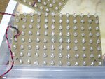
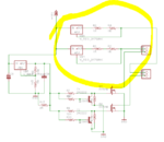
I've been dabbling in electronics for a year or so, and am trying to get my first larger circuit to work properly.. The digital stuff seems simple enough, but analog stuff confuses me") The project is a control circuit for two panels of UV leds for exposing circuit boards. Otherwise everything seems to work OK, but my LM317 regulators don't work as I want them to. I'm trying to achieve a 0.625A current through the led panels, but the LM317's pass through approximately 0.8A (much more with a higher voltage power supply). I've placed 2 1ohm resistors in series between the output and adjustment pins, per the example in the datasheet, but the voltage between the output pin and the adjustment pin doesn't stay at 1.25V.
The project is a control circuit for two panels of UV leds for exposing circuit boards. Otherwise everything seems to work OK, but my LM317 regulators don't work as I want them to. I'm trying to achieve a 0.625A current through the led panels, but the LM317's pass through approximately 0.8A (much more with a higher voltage power supply). I've placed 2 1ohm resistors in series between the output and adjustment pins, per the example in the datasheet, but the voltage between the output pin and the adjustment pin doesn't stay at 1.25V.
I've tried adding filter capacitors to fix the problem -- I've tried placing a 0.1uF, a 100uF and a 1000uF filter capacitor before the regulator, and a 1uF capacitor after the regulator; these didn't have any effect. I've also tried replacing the regulators, and verified that they work in a voltage regulating configuration.
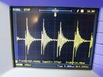
As a power source I'm using a cheap 16V laptop power supply I got off ebay -- could this be a problem?
Also -- the regulators are screwed to a piece of aluminum to act as a heatsink, and they don't get very warm.
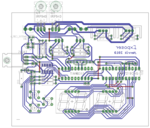
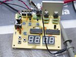
Attached are pictures of the board etc.. The relevant part is a bit messy, since I've been soldering and resoldering it.
Feel free to criticize my board layout etc; I'm not very experienced at this yet
(EDIT: I just noticed it says join date 2006 -- apparently I've been lurking around longer than I thought. Still, I hadn't really made an actual working circuit until last year)
I've been dabbling in electronics for a year or so, and am trying to get my first larger circuit to work properly.. The digital stuff seems simple enough, but analog stuff confuses me
The project is a control circuit for two panels of UV leds for exposing circuit boards. Otherwise everything seems to work OK, but my LM317 regulators don't work as I want them to. I'm trying to achieve a 0.625A current through the led panels, but the LM317's pass through approximately 0.8A (much more with a higher voltage power supply). I've placed 2 1ohm resistors in series between the output and adjustment pins, per the example in the datasheet, but the voltage between the output pin and the adjustment pin doesn't stay at 1.25V.I've tried adding filter capacitors to fix the problem -- I've tried placing a 0.1uF, a 100uF and a 1000uF filter capacitor before the regulator, and a 1uF capacitor after the regulator; these didn't have any effect. I've also tried replacing the regulators, and verified that they work in a voltage regulating configuration.
As a power source I'm using a cheap 16V laptop power supply I got off ebay -- could this be a problem?
Also -- the regulators are screwed to a piece of aluminum to act as a heatsink, and they don't get very warm.
Attached are pictures of the board etc.. The relevant part is a bit messy, since I've been soldering and resoldering it.
Feel free to criticize my board layout etc; I'm not very experienced at this yet
(EDIT: I just noticed it says join date 2006 -- apparently I've been lurking around longer than I thought. Still, I hadn't really made an actual working circuit until last year
)