Continue to Site

Welcome to EDAboard.com

Welcome to our site! EDAboard.com is an international Electronics Discussion Forum focused on EDA software, circuits, schematics, books, theory, papers, asic, pld, 8051, DSP, Network, RF, Analog Design, PCB, Service Manuals... and a whole lot more! To participate you need to register. Registration is free. Click here to register now.

Problem with getting output voltages of ICs in MAX232E circuit

Status
Not open for further replies.

Murtadha

Newbie level 6
Joined
Mar 23, 2010
Messages
14
Helped
0
Reputation
0
Reaction score
0
Trophy points
1,281
Location
Malaysia
Activity points
1,400
hello frindes,
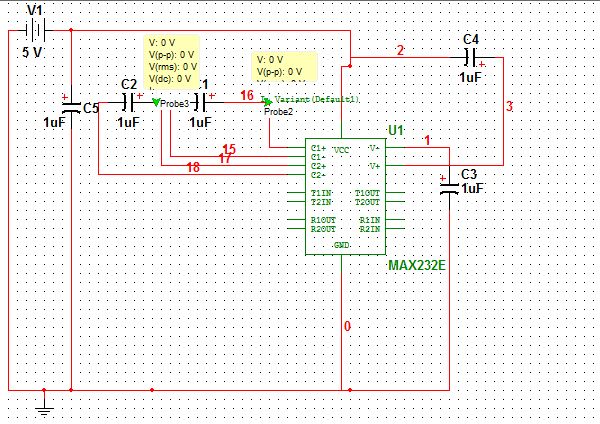
I tried to to get output voltages from the IC's pic but unfortunetly there is no output.
My circuit is like the datat sheet and there is ABSOLUTE MAXIMUM RATINGS
VCC..........................................................................-0.3V to +6V
V+................................................................(VCC - 0.3V) to +14V
V- ............................................................................-14V to +0.3V
Input Voltages
T_IN ............................................................-0.3V to (V+ + 0.3V)
R_IN ...................................................................................±30V
Output Voltages
T_OUT.................................................(V- - 0.3V) to (V+ + 0.3V)
R_OUT......................................................-0.3V to (VCC + 0.3V)

in V+ I got 0 and also in all pins like V- and T_IN

Do you know why?
I went to my teacher and he checked but still the problem


please find the attachment I uploaded
I'm using Multisim 10


thanks alot
 

Problem with MAX232E

Could you post a pdf or jpg or gif of the circuit?

Keith.
 

Problem with MAX232E

Is this something you have built which doesn't work, or are you simulating it?

Keith.
 

Problem with MAX232E

It looks like you have the polarized cap to V- backwards. Note that there are LOTS of ICs with the same pin out as the MAX232E. Most don't require 1 mF caps so you can use 0.1 mF (100nf) ceramic caps which are much smaller, cheaper and non-polarized. The 100 nF is a common decoupling cap.
 

Problem with MAX232E

Dear keith1200rs
I'm using this IC in my project which is PC to PC commuication by fiber
so I have to convert from RS232 level to TTL, I used this IC
When I want to samulating it there is no output voltage.
I must get O/P voltage from some pins
Thanks alot

Dear stephen the obdurate,
thank you
I changed and still the problem
Note: in my project circuit I already change the polarized cap and the mistake only in the circuit, anyway still not working : (
and thanks alot
 

Re: Problem with MAX232E

Murtadha said:
keith1200rs
I'm using this IC in my project which is PC to PC commuication by fiber
so I have to convert from RS232 level to TTL, I used this IC
When I want to samulating it there is no output voltage.
I must get O/P voltage from some pins

What are you using to model the MAX232? I am not aware of there being a Spice model available to simulate it with?

As Stephen said - C3 is the wrong way round. The + end of the capacitor should go to GND.

Keith.
 

Problem with MAX232E

Oh sorry MAX232E not MAX232

I changed it and still the problem !!
I donnn't know where is the problem
I replaced the IC to MAX202E but still no output!!

I'm confused

Added after 2 minutes:

I'm new in Multisim

Added after 37 minutes:

I think the above absolute value is wrong.
Anyone Can read the data sheet and give me the absolute values for MAX232E? please
because I didn't understand the data sheet?

Regards
 

Problem with MAX232E

Sorry, I am still confused.

1. Have you built the circuit (on a circuit board with wires and a power supply)?

2. Are you simulating it in Multisim?

3. If you are simulating it, where did you get the models from?

Sorry if I am sounding a bit dumb!

Keith.
 

Problem with MAX232E

1. Have you built the circuit (on a circuit board with wires and a power supply)?
Yes I have and please visit this topic

2. Are you simulating it in Multisim?
Yes
3. If you are simulating it, where did you get the models from?
Do you mean the IC?
I got it from Master Database>Select Alla groups> then Write MAX ..!
 

Problem with MAX232E

Ok.

Which doesn't work - the actual board, the simulation or both?

I think you misunderstand 'Absolute Maximum Values'. They are the range of voltages that you shouldn't exceed to avoid damaging the device NOT the voltages you would expect to see.

Correct your connection for C3 then measure the voltage on each pin and post the results.

Keith
 

Problem with MAX232E

Keith thanks alot

Can u give me the result for each pin? because I didn't understand the data sheet as u know!\

I have to submit it on Friday!
 

Problem with MAX232E

What I am asking is for you to measure the voltage on each pin. Then I may be able to help work out what is wrong.

Keith.
 

Re: Problem with MAX232E

pin
V- =0
v+=0
C1+ , C1- = 0
C2+ , C2- = 0
R2out= 1.66V
T2in= 1.66 V
 

Re: Problem with MAX232E

You should have something like this:

V+[2] >> ≈ +9Vdc
V-[6] >> ≈ -9Vdc

C1+[1] >> +4Vdc with 0.5Vpp square wave on top of it (dc-offset) ..
C1-[3] >> positive 4.5Vpp square wave

C2+[4] >> positive 4.5Vpp square wave
C2-[5] >> negative 4.5Vpp square wave ..

If you don’t have square waves on C1[+ and -] and C2[+ and -] you will not have double-voltages on V+ and V- ..

Make sure all connections are correct (good idea is to ask someone else to verify your connections), maybe grab new MAX232 and try again ..


Rgds,
IanP
:|
 

Problem with MAX232E

I have submit the report and on Wednesday I have to present.
Vcc is already connected to 5V so it's 5V!
and GND is same

IanP
Can you help me and do this IC in Mutisim, any kind of version 8,9,10 or 11
pleaseeee!!
 

Status
Not open for further replies.

Part and Inventory Search

Welcome to EDABoard.com

Sponsor

Back
Top