Continue to Site

Welcome to EDAboard.com

Welcome to our site! EDAboard.com is an international Electronics Discussion Forum focused on EDA software, circuits, schematics, books, theory, papers, asic, pld, 8051, DSP, Network, RF, Analog Design, PCB, Service Manuals... and a whole lot more! To participate you need to register. Registration is free. Click here to register now.

problem with dspic33fj128gp202 simple code

Status
Not open for further replies.

Tom2

Full Member level 5
Joined
Nov 11, 2006
Messages
318
Helped
3
Reputation
6
Reaction score
3
Trophy points
1,298
Activity points
3,457
I tried to wrote a simple code with dspic33fj128gp202 microcontroller for blinking leds but the code is not working.

Is anyone who know what is going wrong ??
The code which i used is presented :
Code:
#include "p33FJ128GP202.h"
#include <libpic30.h>
#define FCY 40000000UL   // FCY = FOSC/2 = 80Mhz / 2 = 40Mhz
#define __delay_ms(d) __delay32( (unsigned long) (d)*(FCY/1000))


_FOSCSEL(FNOSC_FRC);
_FOSC(FCKSM_CSECMD & OSCIOFNC_OFF & POSCMD_XT);
_FGS(FWDTEN_OFF);
_FWDT(GCP_OFF );

int main (void)
{
        //TRISA = 0xFFFF; 
   	TRISB = 0xFFFF; 


        TRISAbits.TRISA0 = 0;
        TRISAbits.TRISA1= 0;   
    	__delay_ms(1000000);
        TRISAbits.TRISA0= 1;
        TRISAbits.TRISA1= 1;   
        return 0;
}
 

I think

1. TRISA and TRISB should be 0x0000 for output and 0xFFFF for input. If you are driving leds then the pins should be output type.
2. you are actuall changing TRIS value in the following code
Code:
 TRISAbits.TRISA0=0;
        TRISAbits.TRISA1=0;   
    	__delay_ms(1000000);
        TRISAbits.TRISA0=1;
        TRISAbits.TRISA1=1;

actually, you have to change the port value, like

Code:
PORTAbits.RA0=0;
PORTAbits.RA1=0;   
__delay_ms(1000);
PORTAbits.RA0=1;
PORTAbits.RA1=1;

tey to reduce delay from 1000 sec to 1 sec i.e., 1000 ms.
 

I did the changes but when i tried to download it to the microcontroller i get the error :
Target Device ID (00000000) does not match expected Device
ID (06250000).

then when i tried to program it i get the following error: problem_mplab_dspic33_c30.png


What is going wrong ???????
 

Maybe you have selected a different device other than dspic33fj128gp202. Change the device property to dspic33fj128gp202.
 

I did the changes but when i tried to download it to the microcontroller i get the error :
Target Device ID (00000000) does not match expected Device
ID (06250000).

then when i tried to program it i get the following error:View attachment 82859


What is going wrong ???????

In the MPLAB window, go to Configure > Select Device and select dsPIC33FJ128GP202.

As for the code, change it to:
Code:
#include "p33FJ128GP202.h"
#include <libpic30.h>
#define FCY 40000000UL   // FCY = FOSC/2 = 80Mhz / 2 = 40Mhz
#define __delay_ms(d) __delay32( (unsigned long) (d)*(FCY/1000))


_FOSCSEL(FNOSC_FRC);
_FOSC(FCKSM_CSECMD & OSCIOFNC_OFF & POSCMD_XT);
_FGS(FWDTEN_OFF);
_FWDT(GCP_OFF );

int main (void)
{
    TRISA = 0; 
   	//TRISB = 0xFFFF; 
	AD1PCFGL = 0x1FFF;

     while(1){
        LATAbits.LATA0 = 0;
        LATAbits.LATA1= 0;   
    	__delay_ms(1000);
        LATAbits.LATA0= 1;
        LATAbits.LATA1= 1;   
        __delay_ms(1000);
     }
}

Hope this helps.
Tahmid.
 

I did the changes but i see the same results. I don't understand what is the problem
 

what do you mean (Did you set up the hardware properly?) what i have to check?
 

the diagram which i used is :schematic_pickit3.png

- - - Updated - - -

Can you see anything wrong?????????????????
 

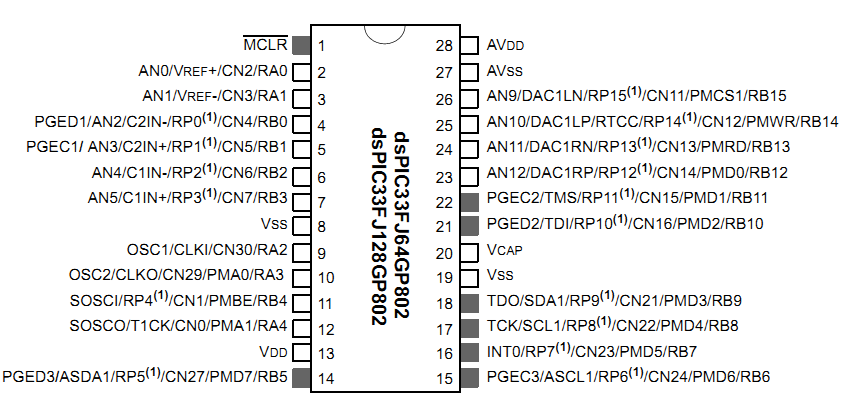
The diagram shows a different processor so check the pins are the same numbers. I do not have the data sheets to hand so they may be OK.
Add a capacitor, I suggest 22pF from each side of the crystal to ground - NEAR THE PIC GROUND PIN - long wires are not acceptable.
R1 may be too high to allow enough programming current. I suggest connecting the Pickit pin 1 directly to the PIC.
The capacitors across the VDD and GND must be conncted as closely to the PIC pins as possible.


The Pickit error indicates it thinks the PIC type you selected doesn't match the one you specified, it has nothing to do with the program itself. It may be that for the reasons mentioned above, it can't actually read the type of PIC connected to it.

Brian.
 

4402556300_1352990497.png


Make sure you've used 3.3V VDD instead of 5V.
Make sure you've connected both VSS pins to ground.
Make sure you've used a 0.1uF bypass/decoupling capacitor, preferably ceramic, from VDD to VSS.
Make sure you've connected AVDD to VDD and AVSS to VSS.
Make sure you've used a 0.1uF bypass/decoupling (ceramic) capacitor, preferably ceramic, from AVDD to AVSS.
Make sure you've connected a capacitor (4.7uF to 10uF) between VCAP and VSS.
Make sure you've pulled up MCLR to VDD with a 10k resistor.

When programming dsPIC33, I had problems with the PICKIT2 recognizing the dsPIC. The solutions to my problems were a 6.8uF capacitor between VCAP and VSS and connections of AVDD and AVSS to VDD and VSS respectively. Ensure that you've made all the connections I mentioned above.

Hope this helps.
Tahmid.
 

Tahmid i tried a lot of values for the Vcap (also 6.8 uf) and also 20K resistor at MCLR but the problem is still there. (I checked all the others things which you said and is ok) I don't understand what is going wrong.

Any other suggestions ?

If i use something like this **broken link removed** will avoid any problems? (this board is work in conjunction with pic kit 3 programmer? )
 

Have you connected -MCLR directly to the Pickit? The pull-up resistor is not needed for programming and should probably be connected to VDD anyway.

Brian.
 

Did you use capacitors from OSC1 to ground and from OSC2 to ground? Check the connections from the crystal oscillator to the dsPIC.
 

Thmid i have already use capacitors OSC1,OSC2 to ground.Also betwixt i have already try to program the microcontroller with out the resistor to MCLR (directly to the Pickit) but the results is the same. I will check again once more my connection but anyway if i use the **broken link removed** i will avoid all these?


(is need also the pic kit programmer to connect to this board? because the connection between the board and the pc is only usb and i can't see how is feasible to connect a pickit 3 programmer to this)
 

The **broken link removed** has an integrate programmer/debugger and should not require the use of a PICkit3.

Reference: Microstick for dsPIC33F and PIC24H Devices Datasheet, Section Overview:

Overview

The Microstick for dsPIC33F and PIC24H devices is designed to provide an easy to
use, economical development environment for 16-bit digital signal controllers and
microcontrollers. The board includes an integrated debugger/programmer, a socket
for the device under test and pins that facilitate insertion into a prototyping board
for extremely flexible development.


It should be noted the dsPIC33FJ128GP202 is not explicitly supported by the Microstick for dsPIC33F and PIC24H:

Supported devices are dsPIC33FJ64MC802, dsPIC33FJ128MC802,
PIC24HJ64GP502, and PIC24HJ128GP502

There are several known issues concerning the PICkit2/3 when programming/debugging the dsPIC33 series.

The exact workarounds for these issues depends on the assembly version of your device. What is the exact assembly version of your PICkit3?

Example:
PICkit 3, Assembly #10-00424-R4

However, most of these issues can be remedied by simply using a proper external power supply to power the dsPIC and associated circuit, rather than using the PICkit3 to supply power.

Also, if your dsPIC is code protected as the message you posted in reply #3 suggests, once you have powered the dsPIC using an separate power supply, manually erasing the entire device should then allow you to program the dsPIC.

Make sure you have not enable code or data protection within the configuration register settings.


BigDog
 

The assembly version of my PICkit3 is : 10-0024-R5 , i will try to use an external power supply for microcontroller, but how to avoid to become a code protected? (i think this is come with the configuration bits, what configuration bits i have to use?????)

Further more there is any other development board which support all(or a lot of) the dspic33 family ????
 

The assembly version of my PICkit3 is : 10-0024-R5 , i will try to use an external power supply for microcontroller, but how to avoid to become a code protected? (i think this is come with the configuration bits, what configuration bits i have to use?????)

More than likely, use of an external power supply to power the device and its associated circuit will remedy the Target Device ID (00000000) error.

Concerning the proper configuration of the configuration register settings, refer to the appropriate device specific header file.

Reference the device specific header file, in this case p33FJ128GP202.h :

Code:
/* -------------------------------------------------------- */
/* Macros for setting device configuration registers        */
/* -------------------------------------------------------- */

/* Register FBS (0xf80000)                               */

extern __attribute__((space(prog))) int _FBS;
#define _FBS(x) __attribute__((section("__FBS.sec"),space(prog))) int _FBS = (x);

/*
** Only one invocation of FBS should appear in a project,
** at the top of a C source file (outside of any function).
**
** The following constants can be used to set FBS.
** Multiple options may be combined, as shown:
**
** _FBS( OPT1_ON & OPT2_OFF & OPT3_PLL )
**
**   Boot Segment Write Protect:
**     BWRP_WRPROTECT_ON    Boot segment is write-protected
**     BWRP_WRPROTECT_OFF   Boot Segment may be written
**
**   Boot Segment Program Flash Code Protection:
**     BSS_LARGE_FLASH_HIGH High Security, Large-sized Boot Flash
**     BSS_HIGH_LARGE_BOOT_CODEHigh Security, Large-sized Boot Flash
**     BSS_MEDIUM_FLASH_HIGHHigh Security, Medium-sized Boot Flash
**     BSS_HIGH_MEDIUM_BOOT_CODEHigh Security, Medium-sized Boot Flash
**     BSS_SMALL_FLASH_HIGH High Security, Small-sized Boot Flash
**     BSS_HIGH_SMALL_BOOT_CODEHigh Security, Small-sized Boot Flash
**     BSS_LARGE_FLASH_STD  Standard Security, Large-sized Boot Flash
**     BSS_STRD_LARGE_BOOT_CODEStandard Security, Large-sized Boot Flash
**     BSS_MEDIUM_FLASH_STD Standard Security, Medium-sized Boot Flash
**     BSS_STRD_MEDIUM_BOOT_CODEStandard Security, Medium-sized Boot Flash
**     BSS_SMALL_FLASH_STD  Standard Security, Small-sized Boot Flash
**     BSS_STRD_SMALL_BOOT_CODEStandard Security, Small-sized Boot Flash
**     BSS_NO_FLASH         No Boot program Flash segment
**     BSS_NO_BOOT_CODE     No Boot program Flash segment
**
**   Boot Segment RAM Protection:
**     RBS_LARGE_RAM        Large-sized Boot RAM
**     RBS_LARGE_BOOT_RAM   Large-sized Boot RAM
**     RBS_MEDIUM_RAM       Medium-sized Boot RAM
**     RBS_MEDIUM_BOOT_RAM  Medium-sized Boot RAM
**     RBS_SMALL_RAM        Small-sized Boot RAM
**     RBS_SMALL_BOOT_RAM   Small-sized Boot RAM
**     RBS_NO_RAM           No Boot RAM
**     RBS_NO_BOOT_RAM      No Boot RAM
**
*/

#define BWRP_WRPROTECT_ON    0xFFFE
#define BWRP_WRPROTECT_OFF   0xFFFF

#define BSS_LARGE_FLASH_HIGH 0xFFF1
#define BSS_HIGH_LARGE_BOOT_CODE 0xFFF1
#define BSS_MEDIUM_FLASH_HIGH 0xFFF3
#define BSS_HIGH_MEDIUM_BOOT_CODE 0xFFF3
#define BSS_SMALL_FLASH_HIGH 0xFFF5
#define BSS_HIGH_SMALL_BOOT_CODE 0xFFF5
#define BSS_LARGE_FLASH_STD  0xFFF9
#define BSS_STRD_LARGE_BOOT_CODE 0xFFF9
#define BSS_MEDIUM_FLASH_STD 0xFFFB
#define BSS_STRD_MEDIUM_BOOT_CODE 0xFFFB
#define BSS_SMALL_FLASH_STD  0xFFFD
#define BSS_STRD_SMALL_BOOT_CODE 0xFFFD
#define BSS_NO_FLASH         0xFFFF
#define BSS_NO_BOOT_CODE     0xFFFF

#define RBS_LARGE_RAM        0xFF3F
#define RBS_LARGE_BOOT_RAM   0xFF3F
#define RBS_MEDIUM_RAM       0xFF7F
#define RBS_MEDIUM_BOOT_RAM  0xFF7F
#define RBS_SMALL_RAM        0xFFBF
#define RBS_SMALL_BOOT_RAM   0xFFBF
#define RBS_NO_RAM           0xFFFF
#define RBS_NO_BOOT_RAM      0xFFFF

/* Register FSS (0xf80002)                               */

extern __attribute__((space(prog))) int _FSS;
#define _FSS(x) __attribute__((section("__FSS.sec"),space(prog))) int _FSS = (x);

/*
** Only one invocation of FSS should appear in a project,
** at the top of a C source file (outside of any function).
**
** The following constants can be used to set FSS.
** Multiple options may be combined, as shown:
**
** _FSS( OPT1_ON & OPT2_OFF & OPT3_PLL )
**
**   Secure Segment Program Write Protect:
**     SWRP_WRPROTECT_ON    Secure segment is write-protected
**     SWRP_WRPROTECT_OFF   Secure segment may be written
**
**   Secure Segment Program Flash Code Protection:
**     SSS_LARGE_FLASH_HIGH High Security, Large-sized Secure Flash
**     SSS_HIGH_LARGE_SEC_CODEHigh Security, Large-sized Secure Flash
**     SSS_MEDIUM_FLASH_HIGHHigh Security, Medium-sized Secure Flash
**     SSS_HIGH_MEDIUM_SEC_CODEHigh Security, Medium-sized Secure Flash
**     SSS_SMALL_FLASH_HIGH High Security, Small-sized Secure Flash
**     SSS_HIGH_SMALL_SEC_CODEHigh Security, Small-sized Secure Flash
**     SSS_LARGE_FLASH_STD  Standard Security, Large-sized Secure Flash
**     SSS_STRD_LARGE_SEC_CODEStandard Security, Large-sized Secure Flash
**     SSS_MEDIUM_FLASH_STD Standard Security, Medium-sized Secure Flash
**     SSS_STRD_MEDIUM_SEC_CODEStandard Security, Medium-sized Secure Flash
**     SSS_SMALL_FLASH_STD  Standard Security, Small-sized Secure Flash
**     SSS_STRD_SMALL_SEC_CODEStandard Security, Small-sized Secure Flash
**     SSS_NO_FLASH         No Secure Segment
**     SSS_NO_SEC_CODE      No Secure Segment
**
**   Secure Segment Data RAM Protection:
**     RSS_LARGE_RAM        Large-sized Secure RAM
**     RSS_LARGE_SEC_RAM    Large-sized Secure RAM
**     RSS_MEDIUM_RAM       Medium-sized Secure RAM
**     RSS_MEDIUM_SEC_RAM   Medium-sized Secure RAM
**     RSS_SMALL_RAM        Small-sized Secure RAM
**     RSS_SMALL_SEC_RAM    Small-sized Secure RAM
**     RSS_NO_RAM           No Secure RAM
**     RSS_NO_SEC_RAM       No Secure RAM
**
*/

#define SWRP_WRPROTECT_ON    0xFFFE
#define SWRP_WRPROTECT_OFF   0xFFFF

#define SSS_LARGE_FLASH_HIGH 0xFFF1
#define SSS_HIGH_LARGE_SEC_CODE 0xFFF1
#define SSS_MEDIUM_FLASH_HIGH 0xFFF3
#define SSS_HIGH_MEDIUM_SEC_CODE 0xFFF3
#define SSS_SMALL_FLASH_HIGH 0xFFF5
#define SSS_HIGH_SMALL_SEC_CODE 0xFFF5
#define SSS_LARGE_FLASH_STD  0xFFF9
#define SSS_STRD_LARGE_SEC_CODE 0xFFF9
#define SSS_MEDIUM_FLASH_STD 0xFFFB
#define SSS_STRD_MEDIUM_SEC_CODE 0xFFFB
#define SSS_SMALL_FLASH_STD  0xFFFD
#define SSS_STRD_SMALL_SEC_CODE 0xFFFD
#define SSS_NO_FLASH         0xFFFF
#define SSS_NO_SEC_CODE      0xFFFF

#define RSS_LARGE_RAM        0xFF3F
#define RSS_LARGE_SEC_RAM    0xFF3F
#define RSS_MEDIUM_RAM       0xFF7F
#define RSS_MEDIUM_SEC_RAM   0xFF7F
#define RSS_SMALL_RAM        0xFFBF
#define RSS_SMALL_SEC_RAM    0xFFBF
#define RSS_NO_RAM           0xFFFF
#define RSS_NO_SEC_RAM       0xFFFF

/* Register FGS (0xf80004)                               */

extern __attribute__((space(prog))) int _FGS;
#define _FGS(x) __attribute__((section("__FGS.sec"),space(prog))) int _FGS = (x);

/*
** Only one invocation of FGS should appear in a project,
** at the top of a C source file (outside of any function).
**
** The following constants can be used to set FGS.
** Multiple options may be combined, as shown:
**
** _FGS( OPT1_ON & OPT2_OFF & OPT3_PLL )
**
**   General Code Segment Write Protect:
**     GWRP_ON              User program memory is write-protected
**     GWRP_OFF             User program memory is not write-protected
**
**   General Segment Code Protection:
**     GSS_HIGH             High Security Code Protection is Enabled
**     GSS_STD              Standard Security Code Protection is Enabled
**     GCP_ON               Standard Security Code Protection is Enabled
**     GSS_OFF              User program memory is not code-protected
**     GCP_OFF              User program memory is not code-protected
**
*/

#define GWRP_ON              0xFFFE
#define GWRP_OFF             0xFFFF

#define GSS_HIGH             0xFFFB
#define GSS_STD              0xFFFD
#define GCP_ON               0xFFFD
#define GSS_OFF              0xFFFF
#define GCP_OFF              0xFFFF

/* Register FOSCSEL (0xf80006)                               */

extern __attribute__((space(prog))) int _FOSCSEL;
#define _FOSCSEL(x) __attribute__((section("__FOSCSEL.sec"),space(prog))) int _FOSCSEL = (x);

/*
** Only one invocation of FOSCSEL should appear in a project,
** at the top of a C source file (outside of any function).
**
** The following constants can be used to set FOSCSEL.
** Multiple options may be combined, as shown:
**
** _FOSCSEL( OPT1_ON & OPT2_OFF & OPT3_PLL )
**
**   Oscillator Mode:
**     FNOSC_FRC            Internal Fast RC (FRC)
**     FNOSC_FRCPLL         Internal Fast RC (FRC) w/ PLL
**     FNOSC_PRI            Primary Oscillator (XT, HS, EC)
**     FNOSC_PRIPLL         Primary Oscillator (XT, HS, EC) w/ PLL
**     FNOSC_SOSC           Secondary Oscillator (SOSC)
**     FNOSC_LPRC           Low Power RC Oscillator (LPRC)
**     FNOSC_FRCDIV16       Internal Fast RC (FRC) divide by 16
**     FNOSC_LPRCDIVN       Internal Fast RC (FRC) with divide by N
**
**   Internal External Switch Over Mode:
**     IESO_OFF             Start-up device with user-selected oscillator source
**     IESO_ON              Start-up device with FRC, then automatically switch to user-selected oscillator source when ready
**
*/

#define FNOSC_FRC            0xFFF8
#define FNOSC_FRCPLL         0xFFF9
#define FNOSC_PRI            0xFFFA
#define FNOSC_PRIPLL         0xFFFB
#define FNOSC_SOSC           0xFFFC
#define FNOSC_LPRC           0xFFFD
#define FNOSC_FRCDIV16       0xFFFE
#define FNOSC_LPRCDIVN       0xFFFF

#define IESO_OFF             0xFF7F
#define IESO_ON              0xFFFF

/* Register FOSC (0xf80008)                               */

extern __attribute__((space(prog))) int _FOSC;
#define _FOSC(x) __attribute__((section("__FOSC.sec"),space(prog))) int _FOSC = (x);

/*
** Only one invocation of FOSC should appear in a project,
** at the top of a C source file (outside of any function).
**
** The following constants can be used to set FOSC.
** Multiple options may be combined, as shown:
**
** _FOSC( OPT1_ON & OPT2_OFF & OPT3_PLL )
**
**   Primary Oscillator Source:
**     POSCMD_EC            EC Oscillator Mode
**     POSCMD_XT            XT Oscillator Mode
**     POSCMD_HS            HS Oscillator Mode
**     POSCMD_NONE          Primary Oscillator Disabled
**
**   OSC2 Pin Function:
**     OSCIOFNC_ON          OSC2 pin has digital I/O function
**     OSCIOFNC_OFF         OSC2 pin has clock out function
**
**   Peripheral Pin Select Configuration:
**     IOL1WAY_OFF          Allow Multiple Re-configurations
**     IOL1WAY_ON           Allow Only One Re-configuration
**
**   Clock Switching and Monitor:
**     FCKSM_CSECME         Both Clock Switching and Fail-Safe Clock Monitor are enabled
**     FCKSM_CSECMD         Clock switching is enabled, Fail-Safe Clock Monitor is disabled
**     FCKSM_CSDCMD         Both Clock Switching and Fail-Safe Clock Monitor are disabled
**
*/

#define POSCMD_EC            0xFFFC
#define POSCMD_XT            0xFFFD
#define POSCMD_HS            0xFFFE
#define POSCMD_NONE          0xFFFF

#define OSCIOFNC_ON          0xFFFB
#define OSCIOFNC_OFF         0xFFFF

#define IOL1WAY_OFF          0xFFDF
#define IOL1WAY_ON           0xFFFF

#define FCKSM_CSECME         0xFF3F
#define FCKSM_CSECMD         0xFF7F
#define FCKSM_CSDCMD         0xFFBF

/* Register FWDT (0xf8000a)                               */

extern __attribute__((space(prog))) int _FWDT;
#define _FWDT(x) __attribute__((section("__FWDT.sec"),space(prog))) int _FWDT = (x);

/*
** Only one invocation of FWDT should appear in a project,
** at the top of a C source file (outside of any function).
**
** The following constants can be used to set FWDT.
** Multiple options may be combined, as shown:
**
** _FWDT( OPT1_ON & OPT2_OFF & OPT3_PLL )
**
**   Watchdog Timer Postscaler:
**     WDTPOST_PS1          1:1
**     WDTPOST_PS2          1:2
**     WDTPOST_PS4          1:4
**     WDTPOST_PS8          1:8
**     WDTPOST_PS16         1:16
**     WDTPOST_PS32         1:32
**     WDTPOST_PS64         1:64
**     WDTPOST_PS128        1:128
**     WDTPOST_PS256        1:256
**     WDTPOST_PS512        1:512
**     WDTPOST_PS1024       1:1,024
**     WDTPOST_PS2048       1:2,048
**     WDTPOST_PS4096       1:4,096
**     WDTPOST_PS8192       1:8,192
**     WDTPOST_PS16384      1:16,384
**     WDTPOST_PS32768      1:32,768
**
**   WDT Prescaler:
**     WDTPRE_PR32          1:32
**     WDTPRE_PR128         1:128
**
**   Watchdog Timer Window:
**     WINDIS_ON            Watchdog Timer in Window mode
**     WINDIS_OFF           Watchdog Timer in Non-Window mode
**
**   Watchdog Timer Enable:
**     FWDTEN_OFF           Watchdog timer enabled/disabled by user software
**     FWDTEN_ON            Watchdog timer always enabled
**
*/

#define WDTPOST_PS1          0xFFF0
#define WDTPOST_PS2          0xFFF1
#define WDTPOST_PS4          0xFFF2
#define WDTPOST_PS8          0xFFF3
#define WDTPOST_PS16         0xFFF4
#define WDTPOST_PS32         0xFFF5
#define WDTPOST_PS64         0xFFF6
#define WDTPOST_PS128        0xFFF7
#define WDTPOST_PS256        0xFFF8
#define WDTPOST_PS512        0xFFF9
#define WDTPOST_PS1024       0xFFFA
#define WDTPOST_PS2048       0xFFFB
#define WDTPOST_PS4096       0xFFFC
#define WDTPOST_PS8192       0xFFFD
#define WDTPOST_PS16384      0xFFFE
#define WDTPOST_PS32768      0xFFFF

#define WDTPRE_PR32          0xFFEF
#define WDTPRE_PR128         0xFFFF

#define WINDIS_ON            0xFFBF
#define WINDIS_OFF           0xFFFF

#define FWDTEN_OFF           0xFF7F
#define FWDTEN_ON            0xFFFF

/* Register FPOR (0xf8000c)                               */

extern __attribute__((space(prog))) int _FPOR;
#define _FPOR(x) __attribute__((section("__FPOR.sec"),space(prog))) int _FPOR = (x);

/*
** Only one invocation of FPOR should appear in a project,
** at the top of a C source file (outside of any function).
**
** The following constants can be used to set FPOR.
** Multiple options may be combined, as shown:
**
** _FPOR( OPT1_ON & OPT2_OFF & OPT3_PLL )
**
**   POR Timer Value:
**     FPWRT_PWR1           Disabled
**     FPWRT_PWR2           2ms
**     FPWRT_PWR4           4ms
**     FPWRT_PWR8           8ms
**     FPWRT_PWR16          16ms
**     FPWRT_PWR32          32ms
**     FPWRT_PWR64          64ms
**     FPWRT_PWR128         128ms
**
**   Alternate I2C  pins:
**     ALTI2C_ON            I2C mapped to ASDA1/ASCL1 pins
**     ALTI2C_OFF           I2C mapped to SDA1/SCL1 pins
**
*/

#define FPWRT_PWR1           0xFFF8
#define FPWRT_PWR2           0xFFF9
#define FPWRT_PWR4           0xFFFA
#define FPWRT_PWR8           0xFFFB
#define FPWRT_PWR16          0xFFFC
#define FPWRT_PWR32          0xFFFD
#define FPWRT_PWR64          0xFFFE
#define FPWRT_PWR128         0xFFFF

#define ALTI2C_ON            0xFFEF
#define ALTI2C_OFF           0xFFFF

/* Register FICD (0xf8000e)                               */

extern __attribute__((space(prog))) int _FICD;
#define _FICD(x) __attribute__((section("__FICD.sec"),space(prog))) int _FICD = (x);

/*
** Only one invocation of FICD should appear in a project,
** at the top of a C source file (outside of any function).
**
** The following constants can be used to set FICD.
** Multiple options may be combined, as shown:
**
** _FICD( OPT1_ON & OPT2_OFF & OPT3_PLL )
**
**   Comm Channel Select:
**     ICS_PGD3             Communicate on PGC3/EMUC3 and PGD3/EMUD3
**     ICS_PGD2             Communicate on PGC2/EMUC2 and PGD2/EMUD2
**     ICS_PGD1             Communicate on PGC1/EMUC1 and PGD1/EMUD1
**
**   JTAG Port Enable:
**     JTAGEN_OFF           JTAG is Disabled
**     JTAGEN_ON            JTAG is Enabled
**
*/

#define ICS_PGD3             0xFFFD
#define ICS_PGD2             0xFFFE
#define ICS_PGD1             0xFFFF

#define JTAGEN_OFF           0xFFDF
#define JTAGEN_ON            0xFFFF

/* Register FUID0 (0xf80010)                               */

extern __attribute__((space(prog))) int _FUID0;
#define _FUID0(x) __attribute__((section("__FUID0.sec"),space(prog))) int _FUID0 = (x);

/*
** Only one invocation of FUID0 should appear in a project,
** at the top of a C source file (outside of any function).
**
** The following constants can be used to set FUID0.
** Multiple options may be combined, as shown:
**
** _FUID0( OPT1_ON & OPT2_OFF & OPT3_PLL )
**
**   :
**
*/


/* Register FUID1 (0xf80012)                               */

extern __attribute__((space(prog))) int _FUID1;
#define _FUID1(x) __attribute__((section("__FUID1.sec"),space(prog))) int _FUID1 = (x);

/*
** Only one invocation of FUID1 should appear in a project,
** at the top of a C source file (outside of any function).
**
** The following constants can be used to set FUID1.
** Multiple options may be combined, as shown:
**
** _FUID1( OPT1_ON & OPT2_OFF & OPT3_PLL )
**
**   :
**
*/


/* Register FUID2 (0xf80014)                               */

extern __attribute__((space(prog))) int _FUID2;
#define _FUID2(x) __attribute__((section("__FUID2.sec"),space(prog))) int _FUID2 = (x);

/*
** Only one invocation of FUID2 should appear in a project,
** at the top of a C source file (outside of any function).
**
** The following constants can be used to set FUID2.
** Multiple options may be combined, as shown:
**
** _FUID2( OPT1_ON & OPT2_OFF & OPT3_PLL )
**
**   :
**
*/


/* Register FUID3 (0xf80016)                               */

extern __attribute__((space(prog))) int _FUID3;
#define _FUID3(x) __attribute__((section("__FUID3.sec"),space(prog))) int _FUID3 = (x);

/*
** Only one invocation of FUID3 should appear in a project,
** at the top of a C source file (outside of any function).
**
** The following constants can be used to set FUID3.
** Multiple options may be combined, as shown:
**
** _FUID3( OPT1_ON & OPT2_OFF & OPT3_PLL )
**
**   :
**
*/

While there are defaults for unspecified Configuration Register settings, I would suggest explicitly disabling or enabling all the available features.

You may want to explicitly disable the JTAG interface as well.

Doing so will alleviate any possible discrepancy and ensure the device is initialized into a know state.


Further more there is any other development board which support all(or a lot of) the dspic33 family ????

All? Most likely not, due to the differences in package styles.

However, there are development boards which many of the family:

Microstick II supports all 3.3V PIC24FJ, PIC24H, dsPIC33, and PIC32 SPDIP packaged devices.

**broken link removed**

The Explorer 16 Dev Boards supports many of the devices in Quad packages:

**broken link removed**


It should also be noted the Vcap requires a low ESR of less than 5Ω and a capacitive value in the 4.7 μF and 10 μF range.

Reference: dsPIC33FJ32GP302/304, dsPIC33FJ64GPX02/X04, and dsPIC33FJ128GPX02/X04 Datasheet, Section: 2.3 CPU Logic Filter Capacitor Connection (VCAP), Page: 20

2.3 CPU Logic Filter Capacitor Connection (VCAP)

A low-ESR (< 5 Ohms) capacitor is required on the
VCAP pin, which is used to stabilize the voltage
regulator output voltage. The VCAP pin must not be
connected to VDD, and must have a capacitor between
4.7 μF and 10 μF
, preferably surface mount connected
within one-eights inch of the VCAP pin connected to
ground. The type can be ceramic or tantalum. Refer to
Section 30.0 “Electrical Characteristics” for
additional information.


BigDog
 

Guys finally I choosed to microstik 2 kit and the problem of the led blinking is solved.

Moreover i move to implement a uart code, for communication with pc and i would like to ask what software (for the PC) is needed to communicate dspic with pc.
(I don't mean the code for programming pic)
 

Status
Not open for further replies.

Part and Inventory Search

Welcome to EDABoard.com

Sponsor

Back
Top