Continue to Site

Welcome to EDAboard.com

Welcome to our site! EDAboard.com is an international Electronics Discussion Forum focused on EDA software, circuits, schematics, books, theory, papers, asic, pld, 8051, DSP, Network, RF, Analog Design, PCB, Service Manuals... and a whole lot more! To participate you need to register. Registration is free. Click here to register now.

Problem with designing filter using fdatool in MATLAB

Status
Not open for further replies.

testing test

Member level 3
Joined
Mar 3, 2010
Messages
65
Helped
5
Reputation
10
Reaction score
3
Trophy points
1,288
Activity points
1,656
Hi,

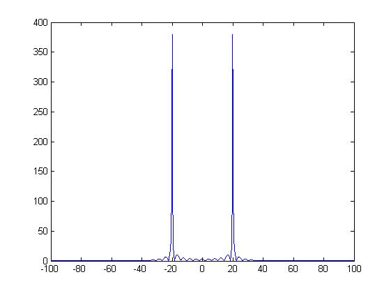
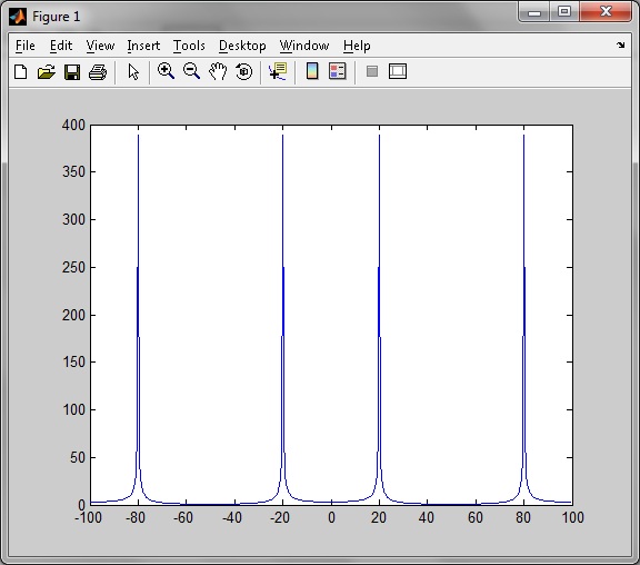
I have first used the following code to generate a signal with two different sinusoid (it worked fine as shown after the code):

clc, clear all;
f1=20;
f2=80;
fs=200;
t=1:1024;
x=sin(2*pi*f1/fs*t)+sin(2*pi*f2/fs*t);
N=1024;
F=fft(x,N);
Fc=fftshift(F);
w=fs*(-N/2:(N/2)-1)/N;
plot(w,abs(Fc));


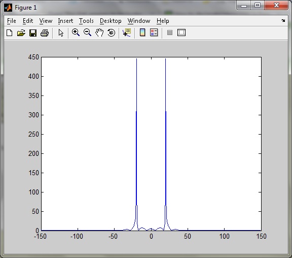
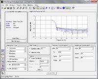
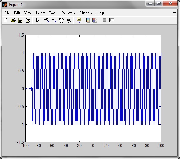
Then as shown in the attached image below, I designed a filter in fdatool.


After designing in fdatool, I returned to workspace and entered the following commands:

y=filter(Num,1,x);
plot(w,y);

This shown me an incorrect distorted filtered shown in figure below.


Please look into the issue. Thank you.
 

I think that your work is ok.
First, one minor correction. In the line when you plot signal "y", you wrote:

plot(w,y);

but it should be

plot(t,y);

since "y" is in the time domain so you should put "t", not "w".

Second, if you preform an FFT of "y" like you did with "x", and plot the result, you will see on the output of filter only signal of 20Hz (and that is ok since you designed filter with Fstop=40Hz), see picture below.


The distortion that you are talking about is consequence of delay introduced by filter. If you take a look at your "fdatool" picture, you'll notice in upper left corner that the order of filter is 101. Help in Matlab says that "filter" command is implemented as "direct form II transposed structure". That means that the output samples of signal "y" in different time moments are:

y(0) = a(0)*x(0)
y(1) = a(0)*x(1) + a(1)*x(0)
y(2) = a(0)*x(2) + a(1)*x(1) + a(2)*x(0)
y(3) = a(0)*x(3) + a(1)*x(2) + a(2)*x(1) + a(3)*x(0)
...
...
(convolution of input samples and filter coefficients)

So, in the beginning only x(0) gives the contribution to the output, and as the time goes, more and more input samples are contributing to the output.
This means that the output signal will depend upon the length of the filter (in this case is 101), filter coefficients, and input samples. In this case, you have lowpass FIR filter, which has linear phase characteristic (constant group delay). In case of IIR filters it is different, but then you won't have linear phase characteristics.

If you specify filter order in "fdatool" to let's say 10, you will see that this "distortion" is very short.

Hope this helps a little
 
Yes, i used the following commands after this and it worked:

y=filter(Num,1,x);
y_fft=fft(y,N);
y_fft=fftshift(y_fft);
plot(w,abs(y_fft));

So, the whole code for filtering composite sine signal in MATLAB using FDAtool via FIR filters is:

Code:
f1=20;
f2=120;
fs=300;
t=1:1024;
x=sin(2*pi*f1/fs*t)+sin(2*pi*f2/fs*t);
y=filter(Num,1,x);
y_fft=fft(y,N);
y_fft=fftshift(y_fft);
plot(w,abs(y_fft));

where Num is obtained from fdatool!

And the output is


Status
Not open for further replies.

Part and Inventory Search

Welcome to EDABoard.com

Sponsor

Back
Top