Continue to Site

Welcome to EDAboard.com

Welcome to our site! EDAboard.com is an international Electronics Discussion Forum focused on EDA software, circuits, schematics, books, theory, papers, asic, pld, 8051, DSP, Network, RF, Analog Design, PCB, Service Manuals... and a whole lot more! To participate you need to register. Registration is free. Click here to register now.

Problem with class B amplifier

Status
Not open for further replies.

julian403

Full Member level 5
Joined
Feb 28, 2014
Messages
254
Helped
1
Reputation
2
Reaction score
1
Trophy points
18
Location
Argentina
Activity points
2,105
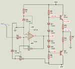
Hi, I'am doing the next amplifier.

diseño.png

Where Vcc=34 V and Vee=-34. The operational it's TL082 and I use a zener diodo to get 16 V for the supply voltage of TL082. But the problem it is that for a input of 1 V and with the configuration of the operational like inversor i have to get 15 V peak on the output of operational but I get 2.5 V peak. Why?

diseño2.png

The input have not offset.
 

Those two diodes on the output don't look right to me. They are both always forward biased, regardless of what the opamp is doing, so you'll have about 100 mA flowing at all times. Also, I'm not sure you won't damage the output stage of your opamp with your arrangement. Maybe try disconnecting those diodes and see what happens.
 

Without a signal, R5, R6 and the diodes have a current of (34V - 0.7V)/330 ohms= 100.9mA.
The output of the opamp might go to 15V when it has no load current. Its minimum output will be about 11V when its output current is only 5mA.

But you want the output voltage of an output transistor to be about 14V peak then its current is 14V/(4 ohms + 0.47 ohms)= 3.13A. The minimum hFE at 3A is 15 so the maximum base current is 209mA.

R5 or R6 certainly cannot supply 209mA and the opamp also cannot supply the very high current.
Replace the TIP41 and TIP42 ordinary transistors with darlington transistors and readjust their bias voltage and current.
 
You was right, I changed to TIP142 and TIP147 it work.

diseño.png

But, there is a form to make it work using tip41 and tip42?. Because, with an hfe of 15, I changed the resistor R6 and R5 to 82 ohms and it still don't work.

Using kirchoff 34- 209[mA]*R-0.7-3.15[A]*4.7ohms ; so R= 91 ohm but I use 82 . I have to work with it. I don't know why not.

Other things, measuring the current in the load, I get

corriente.png
 
Last edited:

With an Hfe of 15, AC output current of 3A, means that the AC input current to the bases must be 3/15 ~ .2A, the TL082 is good for 20mA. So you need a current amplifier between the OP amp and the output pair, this is what the darlington transistor did, its Hfe > 1000?
Frank
 
Ok, I understand. The last question of which I have more fear. For this I have a transformer of +-24 Volt Ac, so when I rectify it I get 34V but the transformer is (what in the box says) for 3 A. I don't know if this 3 A are the total (i means the ampere that flux for ground wire) or there is 3 A for the external wires so in the ground wire there is 6A.

Can I make an stereo?, using the last circuit or I must do a mono?
 

The minimum output voltage from your amplifier is only 11.1V peak which is 7.85V RMS. Then the output power into the 4 ohm load is only 15.4W.
A LOT of transformer power is wasted heating the transistors since the power supply voltages are MUCH TOO HIGH for such a low amount of output power.

If you insist on using the TL081 opamp with its low maximum supply voltages then why don't you make a bridged amplifier?
A bridged amplifier uses two amplifiers, each one driving one wire of the speaker so that the maximum voltage swing in the speaker is about 3.5 times as much as one amplifier. Then the RMS voltage across the speaker will be 7.85V x 3.5= 27.5V RMS and the power in the 4 ohm speaker will be (27.5V squared)/4 ohms= 189W. The power supply voltages can be reduced to about plus and minus 16V and the resistors re-calculated. Then the opamps do not need the zener diodes.

The amplifier heats with almost as much power as the output power so the transformer must be able to provide all that power.
 

Attachments

  • amplifier.png
    amplifier.png
    39.4 KB · Views: 98
Ok, but what do you means with the low maximum supply voltage TL082? I understand that the the max voltage that a TL082 can use is 18V. Or can I put to it 34V? If I can put 34 V to the operational it will be great!

Something like this?

puente.png
 
Last edited:

There was an opamp that had a maximum supply of plus and minus 60V but it was not made often and might not be made anymore. Because its output voltage could be high then its maximum output current was very low to prevent it from too much heating.
 

a bridge like this?

puente.png

But I do not know how to calculate the resistor of the base because i do not know here, in this case, is the ground.
 

Your bridged circuit has no power supply voltages so you cannot calculate the output power and base resistor value.
I notice that the darlington transistors are not included in the feedback loop of the opamp so the distortion will be fairly high. The darlingtons are much slower than the opamp which produces phase shift so you will need a capacitor or two to slow down the opamp to match.
 
Status
Not open for further replies.

Part and Inventory Search

Welcome to EDABoard.com

Sponsor

Back
Top