Continue to Site

Welcome to EDAboard.com

Welcome to our site! EDAboard.com is an international Electronics Discussion Forum focused on EDA software, circuits, schematics, books, theory, papers, asic, pld, 8051, DSP, Network, RF, Analog Design, PCB, Service Manuals... and a whole lot more! To participate you need to register. Registration is free. Click here to register now.

Problem with CAN in LPC2368

Status
Not open for further replies.

mehran123

Member level 1
Joined
Aug 9, 2011
Messages
36
Helped
0
Reputation
4
Reaction score
2
Trophy points
1,288
Activity points
1,514
hi
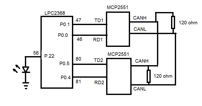
I want make a CAN bus between P0.0,P0.1 and P0.4,P0.5 of LPC2368
I used MCP2551 for physical layer.
Data form TX1 is send,but it doesn't receive to RX2.
TX of micro is connected to pin1 of MCP2551 and RX is connected to pin4.
I used 2 MCP2551,and CANL and CNHH of those are connected together.
I used example of keil for test , then program didn't have any problem.
do you have any idea for test physical layer?
 

I used example of keil for test , then program didn't have any problem.
do you have any idea for test physical layer?

Am I understanding you correctly? It passed the Keil example code. So, does it not function correctly with your code?

If so, can you zip and upload your code or post it, so that we can examine it?


BigDog
 

ok
when data receive to RX2,it will show on lcd.
you can change pins of micro that connected to lcd in "define macros"
 

Attachments

  • test.rar
    108.4 KB · Views: 52

yes
actually i want to connect 2 lpc2368 with CAN together
but because now i haven't 2 board,i have to test it this way
 

I used 2 MCP2551,and CANL and CNHH of those are connected together.

I've not implement a Loopback CAN bus before, I usually make use of a CAN PCI or USB interface on a PC to send and receive data and commands to test a design.

Just to make it clear you are using two MCP2551s attached to the LPC2368 and you have connected CANH to CANH and CANL to CANL between the two MCP2551s, correct?

Have you terminated the CAN bus with a 120Ω resistor? This may or may not be needed, however it would help reduce reflections and unload the open collector transceiver units. Using one resistor should be sufficient with such a short run.

can-term.gif


When running Full CAN (ISO 11898-2) at its higher speeds it is necessary to terminate the bus at both ends with 120 Ohms. The resistors are not only there to prevent reflections but also to unload the open collector transceiver drivers. We recommend that you terminate the bus correctly in all circumstances.

BigDog
 

I has connected CANH to CANH and CANL to CANL and resistor there is in board.
do you have any program that you tested it and it worked?
if you have it,please upload it ,then i will test it on my board.
did you test my codes and did that work?
 

Unfortunately, I do not have any loopback CAN bus code laying around. As I mentioned before I've never attempted to implement such a device. You mentioned you were able to transmit and receive packets successfully, that being the case I would imagine it works.

When I get the chance I'll take a look at your code.

BigDog
 
Hi
I draw may schematic in paint.

Vss and Vcc of LPC2551 are connected to +3.3v and GND, respectively and crystal is 12M.
VDD and GND of MCP2551 are connected to +7v and ground ,respectively and pin RS is connected to GND.

and I changed my codes:
Code:
#include <LPC23xx.h>

void CAN1IRQ (void)
{
IOSET0	|=(1<<22);
CAN1CMR =0x00000004;
VICVectAddr =0x00000000;
}
int main (void)
{
unsigned int i=1;
unsigned int delay=0;
IODIR0 |=(1<<22);
IOCLR0 |=(1<<22);
//------- initialize CAN2---------//
PINSEL0 |=0x2<<8|0x2<<12;
PCONP |=0x1<<14;
CAN2MOD |=0x00000001;
CAN2BTR =0x0B | 0x05<<16 |0x02<<20;
CAN2MOD =0x00000000;
//---------initialize CAN1---------//
PINSEL0 |=0x5;
PINSEL0 |=0x1<<13;
CAN1MOD |=0x00000001;
CAN1BTR =0x0B|0x05<<16 |0x02<<20;
CAN1IER =0x00000001;
VICVectPriority23 =0x00000000;
VICVectAddr23 =(unsigned)CAN1IRQ;
VICIntEnable =0x00800000;
CAN_AFMR =0x00000003;
//--------transfer data-----------//
CAN2TFI1 =0x00040000;
for(i=1;i<0x00000100;i=i<<1)
{
CAN2TID1=i;
if(CAN2SR&0x00000004)
{
CAN2TDA1=i;
CAN2CMR=0x0000021;
}
for(delay=0;delay<0xA0000;delay++);
}
while(1);
}

when data from RX2 received to RX1,LED should be on.
I debugged codes with simulator of keil and it shows that data can transfer,but i can't test receive of data.
but when i programmed chip,it didn't work.
I haven't resistor 120ohm,then i used 270 ohm,can it make problem?
or my codes are incorrect?
what do you think?
 
Last edited:

Status
Not open for further replies.

Similar threads

Part and Inventory Search

Welcome to EDABoard.com

Sponsor

Back
Top