Continue to Site

Welcome to EDAboard.com

Welcome to our site! EDAboard.com is an international Electronics Discussion Forum focused on EDA software, circuits, schematics, books, theory, papers, asic, pld, 8051, DSP, Network, RF, Analog Design, PCB, Service Manuals... and a whole lot more! To participate you need to register. Registration is free. Click here to register now.

Problem with a MOVLW in a code for PIC16f627A

Status
Not open for further replies.

noddls

Newbie level 3
Joined
Jul 16, 2010
Messages
3
Helped
0
Reputation
0
Reaction score
0
Trophy points
1,281
Activity points
1,315
MOVLW on PIC16f627A

Hi there,

This is my first post! Im new to microcontrollers. I was able to download a file and modify the way i want it using PIC16F84A. I got excited so I decided to buy another 16f84 for a new program but there's no stock of this PIC to where I used to buy it, so i ended up uying PIC16F627A (that's the only available). I know that PIC16f627 has more functions than PIC16F84 so i decided to test first if i could directly port the working program i made for PIC16F4A.
At first I cant make an output to PORTA, then i read the DATAsheet and found that comparator should first be disabled. so I did it.
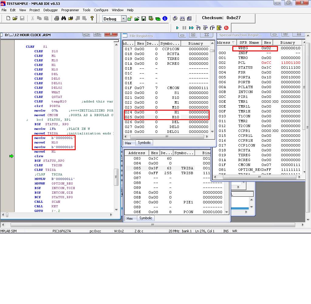
I am using the MPLAB for simulation, and strange as it seem that i am not able to load to the my designated register the value of W. Is there anything I am missing? Here is the code
clrf PORTA
movlw 07h ;++++INITIALIZING PORTA++
movwf CMCON ;PORTA AS A REGULAR OUTPUT
; bcf STATUS, RP1
BSF STATUS, RP0
movlw 1Fh ;PLACE IN W
movwf TRISA ;initializiation ends here
movlw b'00000001'
movwf H10
movlw b'00000010'
movwf H1
clrw
on the simulation image i am already at clrw and nothing is loaded to my H1 and H10 variables.
Please help, is there any initialization I should do?
Thanks, i appreaciate any response.


Re: MOVLW on PIC16f627A

Hi,

The reason it does not work is that you have set things to Bank1 for the TRISA statement, but have not returned to Bank0 afterwards.

If you look at memory address 0A0 and 0A1 you will see the data has been placed there, the start of Bank1 ram.

To correct simply set the Banking back to Bank0, using the Banksel is clearer that the BSF instructions.


Code:
	clrf PORTA
	movlw 07h 			;++++INITIALIZING PORTA++
	movwf CMCON 		;PORTA AS A REGULAR OUTPUT
	banksel TRISA
	movlw 1Fh 			;PLACE IN W
	movwf TRISA 		;initializiation ends here
	banksel 0

	movlw b'00000111'
	movwf H10
	movlw b'00000011'
	movwf H1
	end
 

Re: MOVLW on PIC16f627A

It's very difficult to say what is wrong in such a short section of code but my guess would be that you have the banking bits set wrongly. Possibly labels H1 and H10 are not in bank 1 which is where you are writing to.

Some suggestions:

1. use meaningful names for labels, H1 and H10 may refer to units and tens of hours or they could be something else. If that's what they are, use Hours_Tens and Hours_Mins or something similar to make it more obvious.

2. Instead of setting/resetting the RP0 and RP1 bits, use the 'banksel' directive instead. It makes it much easier to follow the program and the assembler will substitute the correct RP0 and RP1 instructions for you. For example:
Code:
banksel TRISA
movlw 1Fh
movwf TRISA
movlw b'00000001'
banksel H10
movwf H10

will ensure the correct bank for TRISA and for H10 are selected. When you look at the source code you will find the correct RPx setting code has been placed instead.
You only need to use banksel when you know there is a change of bank but initially putting it in front of all registers will still work at the expense of code size. You can always remove them afterward if you decide they are not needed.

3. When pasting code here, click on the box holding the word 'Code' above the message window before and after the code you copy. This tells the forum software to leave any formatting in your program alone so we can see it exactly as you wrote it. This is what I did above to show your code and you should see it in a different background color.

Brian.
 

MOVLW on PIC16f627A

Thanks, I already figured it out by just staring at the address map. For the 16f84 it work without selecting banks, though has a warning during compiling. LOL.. I usually dont care with it as long as the simulation is ok. mmm this 16f627 is much more complicated I guess. I need to thinker with this much further. But I got it working now. Will look for some other applications that might interests me for this PIC. Thanks for the help I appreciate the coding advise.
 

Re: MOVLW on PIC16f627A

Hi,

Well its good you have sorted the problem out for yourself.

The Accessed banking of bank0 and 1 on the 16F84 is now the exception rather than the rule, so you really do need to understand how to use the banking for the SFR and User Registers as this is the way most 16F chips work.

You will find plenty of projects out there, many of the old '84 programs can be easily converted to the 627 and its bigger brother the popular 628/A.

While the 627/628 are so much better as they have the on board oscillator etc you might find the 16F88 chip even better as it has onboard 10bit ADC which allows you to do so much more with input devices.
 

Status
Not open for further replies.

Similar threads

Part and Inventory Search

Welcome to EDABoard.com

Sponsor

Back
Top