doug08
Junior Member level 3
According to the spec sheet, you can put up to 2A current from C to E. I never saw it go above 450ma. What is the maximum current you draw on your circuit?
Follow along with the video below to see how to install our site as a web app on your home screen.
Note: This feature may not be available in some browsers.
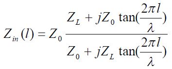
You are confused.To calculate the VSWR, you need to calculate the impedance transformation based on the 75ohm segment's length. Here it is very short compared to the wavelength, so it doesn't really matter what connectors you have, as long as the lines and the input/output terminations at the end of the line agree.
You are confused.
No, I am a microwave engineer who learned about these things.
Your calculation is nonsense. The input impedance into a line with mixed impedances depends on the line length. If the length is short, Zin=Zload regardless of the line Z0.


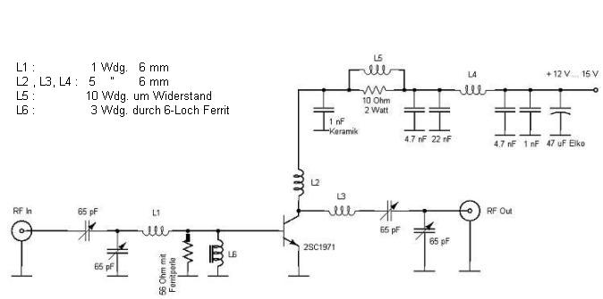
This happens due to increased parasitic feedback throgh air. Set finally local oscillator to desired frequency after fitted in box.One problem, the RF amplifier is lowering the input frequency by 2 MHZ.