gribi20
Member level 2
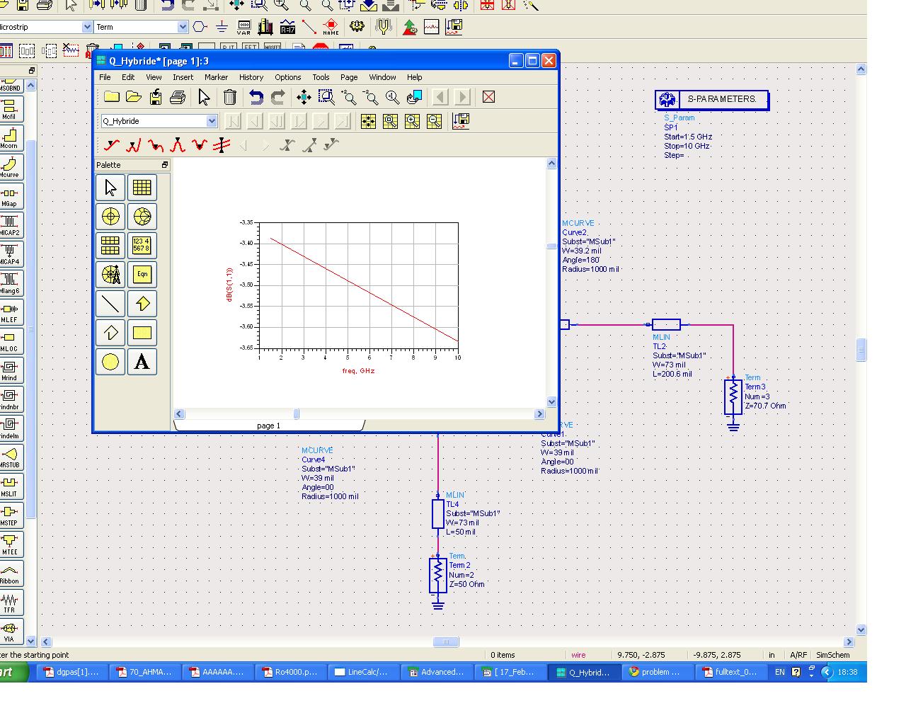
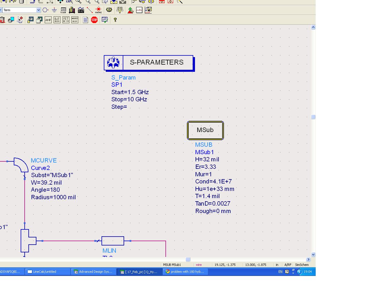
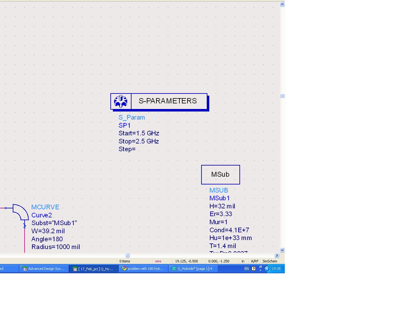
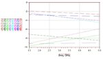
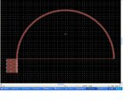
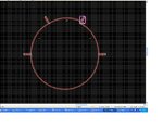
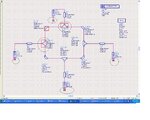
Im designing a 180 Hybride coupler https://obrazki.elektroda.pl/15_1303837015.jpg
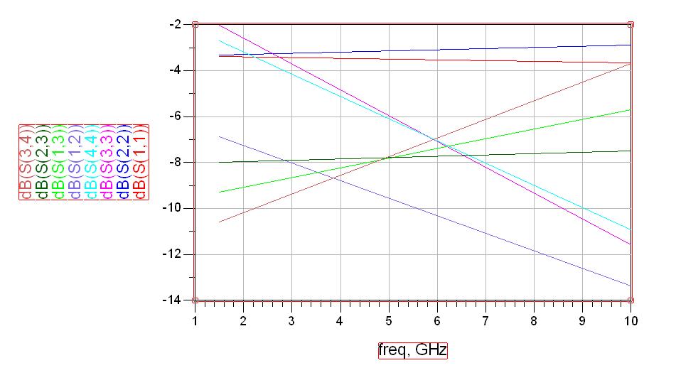
but this design im doing just taken from one project from the internet in ADS the out put i have is totally different .plz can any body check this one
but this design im doing just taken from one project from the internet in ADS the out put i have is totally different .plz can any body check this one
 z= 50 ohm