Continue to Site

Welcome to EDAboard.com

Welcome to our site! EDAboard.com is an international Electronics Discussion Forum focused on EDA software, circuits, schematics, books, theory, papers, asic, pld, 8051, DSP, Network, RF, Analog Design, PCB, Service Manuals... and a whole lot more! To participate you need to register. Registration is free. Click here to register now.

Problem: Varactor Based Phase Shifter Design

Status
Not open for further replies.

waqasbee4

Newbie level 4
Joined
Nov 14, 2010
Messages
7
Helped
0
Reputation
0
Reaction score
0
Trophy points
1,281
Activity points
1,327
I want to design a Phase Shifter at 10 GHz using FR4.
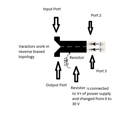
I am using branchline coupler followed by two varactors at port 2 and 3 (port 1 is input and 4 is output).

39_1305731595.jpg


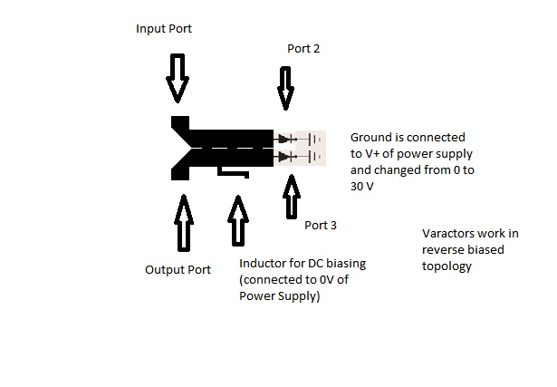
Although FR4 is not suitable for high frequencies but I am getting S11 and S22 below -14db at 10 GHz

The problem is in Phase of S21,
I am getting no phase change at 10 Ghz in whole biasing range

Instead I am getting phase change at 2 GHz (around 40 degrees phase shift)

varactor diode supports upto 12Ghz frequency.

I cannot figure out any mistake

Need help urgently!
 

The shape in the picture is not a branch line coupler.
To bias the varactors, instead using an inductor connected to the middle of the coupler, try using two resistors (~100k)
 

that might be a branchline coupler if all the sections of line were around quarterwavelength long at 10 ghz.

But squinting my eyes and trying to envision a branchline hybrid out of what you drew, it looks like you have one of the varactors on the wrong port.
 

Its is a 180 degree coupler/ rat race coupler (branch line not circular!)
I am using microstrip inductor for blocking ac and otherwise it will travel to my power supply
 

Its not a rat race coupler either.

Looks like it is a version of a Schiffman phase shifter.
**broken link removed**

The 100k resistor (or two) would block the AC also, and more than this, do not have cut-off frequencies or parasitic resonant frequencies as an inductor.
 
I am going to use 100k Resistors and will inform about results.

Fingers Crossed!
 

I checked the design using 100k resistor

43_1305813285.jpg


Now although S-Parameters are Still fine

S11:-22 dB
S22:-18 dB
S21:-6.4 dB

But now phase shift is restricted to 1 GHz only (Previously 2.2 GHz)

Please Advise!

Need urgent help
 

I don't have an answer, having only the information you give.

The quadrature phase shifter can provide almost any desired phase shift, but the loads should present purely reactive impedances.

I am not sure you are using the right design for the coupler. Try to make a standard branch line coupler (as in the picture)

56_1305829149.gif
 

Initially I tried Standard Branch line coupler but i was unable to achieve desired S11 at 10 Ghz
Standard Branch Line Coupler has less bandwidth, my design is a modification of standard branch line coupler.
By adding one segment to it, its bandwidth increases

So my modified design performs same (with some compromise on coupling)
 

Status
Not open for further replies.

Part and Inventory Search

Welcome to EDABoard.com

Sponsor

Back
Top