Continue to Site

Welcome to EDAboard.com

Welcome to our site! EDAboard.com is an international Electronics Discussion Forum focused on EDA software, circuits, schematics, books, theory, papers, asic, pld, 8051, DSP, Network, RF, Analog Design, PCB, Service Manuals... and a whole lot more! To participate you need to register. Registration is free. Click here to register now.

[AVR] Problem using TX-Rx pins

Status
Not open for further replies.

Vahid_h

Newbie level 4
Joined
Dec 27, 2017
Messages
6
Helped
0
Reputation
0
Reaction score
0
Trophy points
1
Activity points
54
Hi everyone,
I'm simply trying to send a number (for example 1) from a Mega16 to another Mega16 using Tx and Rx pins.
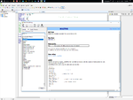
I used this code in Transmitter side:

Dim L as Byte
L=1
...
Print L

and in receiver side:

Dim L as Byte
....
Input L
cls
LOCATE 1,1
LCD L[/INDENT]


But I cant see the correct number (1) in LCD.

Why????!!:thinker:
I know my lcd configuration and wiring is correct.
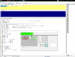
I checked transmitted and received signal in scope and attached is the result.
ScreenHunter 07.jpg
Thanxxxxx
 

Thank you!:thumbsup:
I think you meant the HEX representation.

So, to just display the received number ("1" in this case) on LCD, should I convert it to decimal in Receiver?I mean how can I display received data on LCD in correct format (decimal)?
 

Need to learn the meaning of Basic print and input instructions. The quoted instruction prints 0x31, 0x0d, 0x0a the decimal representation of the number with carriage return line feed. "1",<CR>,<LF>

First point is to check if the number string is correctly received with the input instruction, second if LCD L does what you want.

- - - Updated - - -

No, the "printed" number string is decimal.

I don't know anything about the used BASIC compiler and its non-standard instructions, e.g. LCD related. You also didn't show how the serial interfaces are set up.
 
It's difficult to interpret the scope waveform but clearly there is more than one character being sent. Each character normally needs 10 bits, start bit, 8 data bits and a stop bit. Normal serial data does not return to zero at each bit boundary, it relies only on the duration of each high and low to tell how many 1's or 0's it represents.

LCDs usually use ASCII so the value '0x01' has to be converted to '0x31' to make it display as character '1' but not all LCD modules follow that rule. Without knowing the details of your compiler (or interpreter) we can't tell if the value is already converted by the 'Print' command. For example, does your "Print L" send 0x01 or has it already converted it for printing as 0x31?

If you really want to send the value 0x01 there is probably a different command to send 'raw' data.

Brian.
 
It's difficult to interpret the scope waveform.
I already decoded it as 0x31, 0x0d, 0x0a (at 150 Baud N,8,1). That's what print 1 or print L is expected to send. (I used BASIC 35 years ago).

The question is, if it's correctly received as decimal 1 by the input instruction.
 
(I used BASIC 35 years ago).
That means you are probably younger than me!
It's a horrible language. I commend you on your eyesight and patience to decode it.


Vahid_h ,possibly the extra two characters are interfering with the display. Try filtering out characters with values below 0x20 (32 in decimal) so they are not sent to the LCD.

Brian.
 
Which Compiler used ? Bascom AVR ? If BASCOM AVR then I can help.
 

Thank you Brian for your time and help,

I use BASCOM AVR and a normal 16*2 LCD that I can display every character on that. For instance:

LCD "LL" ' It shows LL on LCD
LCD 45 ' It shows 45
LCD L ' Compiler asks to define L

dim L as byte
L=1
LCD L 'Shows 1

I have no problem in using this LCD in normal applications, but when I receive any character from RX ... That's where the problem begins. How should I show that charachters on the LCD?

Thank you again for your time and I so much appreciate your way of talking ;-);-)
 

"LL" is a string and it will be terminated with a null string = '\0' character.

45 is a number and maybe BASCOM AVR LCD function can convert number (integer) to string and display it also.

'L' is a character and you should see if there is a function in LCD library which can display character.

If you are receiving single character using UART then you just need to send that character to Lcd character display function.

If you are receiving 'L', )x0D, 0x0A into 1 byte variable using interrupt then your 'L' and 0x0D character will be overwritten with 0x0A the last character received using serial interrupt. Maybe this is causing the problem.

Can you zip and post your complete BASCOM AVR project so that I can help you with the code ?
 

Actually I want to send an output of a sensor from transmitter side to receiver side, which is only a one byte number ( always between 0 to 256).

Your comment: If you are receiving 'L', )x0D, 0x0A into 1 byte variable using interrupt then your 'L' and 0x0D character will be overwritten with 0x0A the last character received using serial interrupt. Maybe this is causing the problem. is interesting and I already was thinking about hat, but in any case I think it should send "something" to the LCD, But It shows only 0.

I also used Long and Word instead of byte with the same result.

Thanx
 

Dim L as byte will never work if you send 'L', 0x0D and 0x0A. Variable L will then hold 0x0A after receiving serial data.

You should use a array to hold all the received characters and then strip of the 0x0D and 0x0A from it and terminate the array with null character to convert it to string and display the string.

You have to check serialinput.bas example project to use interrupt service routine for serial communication. You have to use serial interrupt communication on the receiver to receive all the characters sent from the transmitter into an array and then stop receiving characters when 0x0D or 0x0A is received and terminate the array with null character to convert it to a string and then display the array on lcd.

From transmitter are you sending the 1 byte value (0 to 255) as a integer or string ? Are you also sending <CR> <LF> at the end of the serial transmission ?
 
Last edited:

Im sending it as an Integer and I assume by default CR/LF are sent.

But , what if I try to avoid sending them using this comment from avrhelp.mcselec.com:

Print “ABC” ;

When we type a semicolon ( ; ) at the end of the line...

Bascom does not send a carriage return/line feed, so you can print another text after the ABC on the same line.


Then I can use Waitkey command to just detect my only byte that is coming.
 
Last edited:

Yes, you can try that.

Here is the test code which I made. My code still doesn't use interrupts for receiving serial data. It uses polling method. The lcd code in my code is working only in Bascom AVR simulator. It is not working in Proteus. I have not tested the codes on hardware. I am new to Bascom AVR.

Transmitter.


[/code]

Thanx baileychic, I'll try that code also on my hardware with some lower Baudrates.:thumbsup:
 

Yes, you can try that.

Here is the test code which I made. My code still doesn't use interrupts for receiving serial data. It uses polling method. The lcd code in my code is working only in Bascom AVR simulator. It is not working in Proteus. I have not tested the codes on hardware. I am new to Bascom AVR.

Transmitter.

Code:
$regfile = "m16def.dat"
$crystal = 4000000
$Baud = 9600
$sim
$lib "lcd4.lbx"                                             ' use the alternative library
$hwstack = 40
$swstack = 40
$framesize = 40

'in order for simulation to work correct, you need to specify the used pins
'for lcd4.lbx, the pins are fixed
'Rs = PortB.0
'RW = PortB.1        we dont use the R/W option of the LCD in this version so connect to ground
' E = PortB.2
'E2 = PortB.3        optional for lcd with 2 chips
'Db4 = PortB.4       the data bits must be in a nibble to save code
'Db5 = PortB.5
'Db6 = PortB.6
'Db7 = PortB.7

Config Lcdpin = Pin , Rs = Portb.0 , E = Portb.2 , Db4 = Portb.4 , Db5 = Portb.5 , Db6 = Portb.6 , Db7 = Portb.7

Waitms 200

Config Lcd = 16x2

Dim count as byte

DDRB = $FF
PORTB = $00

Cls
Locate 1 , 1 : Lcd "ATmega"
Waitms 50
Locate 1 , 7 : Lcd 16
Waitms 50
Locate 1 , 10 : Lcd 4
Waitms 50
Locate 1 , 11 : Lcd "M"
Waitms 50
Locate 1 , 12 : Lcd "H"
Waitms 50
Locate 1 , 13 : Lcd "z"
Waitms 50

count = 255

Do

   Print str(count)
   Print $0D
   Print $0A
   Waitms 1000
   count = count + 1

   Locate 2 , 8 : Lcd str(count)
Loop

End


Receiver

Code:
$regfile = "m16def.dat"
$crystal = 4000000
$Baud = 9600
$sim
$lib "lcd4.lbx"                                             ' use the alternative library
$hwstack = 40
$swstack = 40
$framesize = 40

'in order for simulation to work correct, you need to specify the used pins
'for lcd4.lbx, the pins are fixed
'Rs = PortB.0
'RW = PortB.1        we dont use the R/W option of the LCD in this version so connect to ground
' E = PortB.2
'E2 = PortB.3        optional for lcd with 2 chips
'Db4 = PortB.4       the data bits must be in a nibble to save code
'Db5 = PortB.5
'Db6 = PortB.6
'Db7 = PortB.7

Config Lcdpin = Pin , Rs = Portb.0 , E = Portb.2 , Db4 = Portb.4 , Db5 = Portb.5 , Db6 = Portb.6 , Db7 = Portb.7
Config Serialin = Buffered , Size = 20

Config Lcd = 16x2

Dim uart_rd(4) as byte
Dim I as Integer

Cls
Locate 1 , 1 : Lcd "ATmega"
Locate 1 , 7 : Lcd 16
Locate 1 , 10 : Lcd 4
Locate 1 , 11 : Lcd "M"
Locate 1 , 12 : Lcd "H"
Locate 1 , 13 : Lcd "z"

Enable Interrupts

Do

If Ischarwaiting() = 1 Then                             'was there a char?
   uart_rd(I) = Ischarwaiting()

   If uart_rd(I) = $0D or uart_rd(I) = $0A Then
      I = 0
   Else
      I = I + 1
   End If

   uart_rd(I) = 0
EndIf

Locate 2 , 1 : Lcd uart_rd

Loop

End

- - - Updated - - -

Check your PM (private message).
 

I very will know how to write bascom avr code (one of which I posted) but as the bascom avr compiler's delay function doesn't generate proper delays as mentioned in its help file the lcd code never worked for me in Proteus and also hardware. I just tested the bascom avr project that I made for the OP on hardware. Lcd remains blank. I will post the bascom project and proteus file in a few minutes.

Find the attached bascom project files and Proteus simulation file. The code only works in Bascom AVR simulator.
 

Attachments

  • waitms.png
    waitms.png
    110 KB · Views: 79
  • bascom avr simulator.png
    bascom avr simulator.png
    93.8 KB · Views: 87
  • Vahid_h.rar
    29.5 KB · Views: 59
Last edited:

Status
Not open for further replies.

Similar threads

Part and Inventory Search

Welcome to EDABoard.com

Sponsor

Back
Top