Continue to Site

Welcome to EDAboard.com

Welcome to our site! EDAboard.com is an international Electronics Discussion Forum focused on EDA software, circuits, schematics, books, theory, papers, asic, pld, 8051, DSP, Network, RF, Analog Design, PCB, Service Manuals... and a whole lot more! To participate you need to register. Registration is free. Click here to register now.

Problem in Zero Crossing Detector(ZCD) Circuit

Status
Not open for further replies.

rushi53

Member level 2
Joined
Aug 19, 2009
Messages
46
Helped
2
Reputation
4
Reaction score
1
Trophy points
1,288
Location
India
Activity points
1,632
Hi,

I am working on "Temperature controlled Fan using 89s51". Requirement is: Fan speed should vary depending upon temperature variations.
I am using Triac BT136 for controlling fan speed, I am varying the firing angle for triac.
Zero crossing detector (ZCD) is used here.

I am working on 230vAC/50Hz power supply, which means ZCD should give 50pulses per second.
My problem is that ZCD is not giving 50 pulses. (It gives approx 35,000 pulses per second)

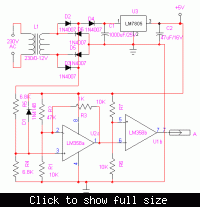
I am uploading the circuit diagram of ZCD. Output terminal A goes to interrupt0 of microcontroller (89s51)

Please help me to correct the ZCD diagram. Or please suggest me any replacement for this.


I have personally tried the said circuit and from www.8051projects.info works perfectly well without any problems. You may also try single transistor circuit given in the blogs and Forums in the same website. On the other hand, you may also have a look at completely assembled and tested a similar project of a complete switch board with fan regulator at www. united77.com/projects.htm. Cheers
 

    rushi53

    Points: 2
    Helpful Answer Positive Rating
I have prepared a PCB from this circuit diagram and tested with a frequency counter program.
It was not giving 50 pulses per second.
I am really confused on this. I need to complete this project by 10th Nov.
Should I prepare the PCB again ?
 

As there will be two zero crossings per cycle, the zerocross detector output shud show 100Hz on a multimeter. Check out for the same. There may be some hardware /assembling problems. Cheers
 

It gives approx 35,000 pulses per second
Sounds unlikely. You may get multiple pulses at zero crossings, because the comparator misses a hysteresis, but not that amount.
I also don't completely understand your circuit dimensioning. R3 is so low, that the first OP mainly works as a buffer
rather than an amplifier. I guess, you messed up the original circuit in this point. But it should work somehow anyway.

To check the circuit operation, an oscilloscope would be the appropriate instrument.
 

Hi Guys,

Problem is solved now...

Actual defect was in microcontroller program.
Previously I have cleared IT0 bit of TCON register.
But then I set that bit to 1 and now circuit is giving 100 pulses per second.

I must say thanks to "pranam77"
He gave me confidence that hardware is correct, so I started looking into programming and found the defect. Thank you very much...
 

Status
Not open for further replies.

Part and Inventory Search

Welcome to EDABoard.com

Sponsor

Back
Top