Continue to Site

Welcome to EDAboard.com

Welcome to our site! EDAboard.com is an international Electronics Discussion Forum focused on EDA software, circuits, schematics, books, theory, papers, asic, pld, 8051, DSP, Network, RF, Analog Design, PCB, Service Manuals... and a whole lot more! To participate you need to register. Registration is free. Click here to register now.

[SOLVED] Problem in Wireless Transmitter and Receiver

Status
Not open for further replies.

speedEC

Full Member level 6
Joined
Apr 1, 2011
Messages
337
Helped
23
Reputation
46
Reaction score
21
Trophy points
1,298
Activity points
4,324
Dear All,

need a help to build simple wireless transmitter and receiver. I bought one wireless tx and rx (pair) and also HT12E and HT12D. I have connected all as per the circuit given at "roboticsy.blogspot.com". But I didn't get any result. Pl see the circuit design. I have used 1K in Transmitter and 56K in Receiver Circuit. I connected LED at pin 13 of HT12D (D0). The LED did not light-up. Also, I have connected LED at the pin 17 (VT) of HT12D thro' 2N3904 transistor. If the HT12D receive the valid signal, the VT pin goes high. If so, The connected LED should also light up. But, it also didn't.

Pl note:

1. I have used only one switch instead of 4 switches shown in circuit diagram of transistor.
2. I used 1/22 wire as antenna and their length is around 15cms each.
3. I have used Bread Board
4. I have placed both the transmitter and receiver in a same bread board
5. I left unconnected the pins 1-8 of HT12E and also HT12D.
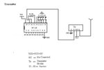
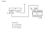
tx12e.JPG RX12D.JPG

Can anyone able to help me in this regard?

Advance thanks.
 

Are you using a 1K Ω resistor as stated in your post or a 1M Ω resistor as shown in the schematic on pins 15 and 16 of the HT12E?

John
 
Thanks John. Yes. I have used 1K ohm resistor on Transmitter side and 56K ohm resistor on receiver side. Also, I read the Dout Pin on HT12D. It reads between .98v to 1.34v when TE pin of HT12E not grounded and reads around 1.90v when TE pin grounded. So, I think it receives but may be mismatching occurs. Any help?
 

you should use 1M ohm instead of 1K ohm.
 

Should I use 1M Ohm Resistor?

---------- Post added at 18:38 ---------- Previous post was at 18:30 ----------

OK mr. John. I will change the resistor as you suggested and update you by within few hrs. Until then, thanks and bye.
 

For a 56K resistor on the 12D (decoder), use a 1 M or 750K (recommended by Renolds Electronics) on the encoder. Check the datasheets for the HT12E and HT12D. The decoder oscillator must be about 50X the encoder oscillator frequency. 56K will give a somewhat less than 150 KHz, so the encoder (transmitter) must be about 3 KHz. 1M gives 3 KHz; 1K is not even on the chart. All estimates based on 5V supply.

John

Edit: Here a link to the decoder datasheet: HT12D pdf, HT12D description, HT12D datasheets, HT12D view ::: ALLDATASHEET ::: The encoder is also on that site.
 
Last edited:

The circuits you have posted is correct as per my assumptions. The HT12E should have an oscillator resistor of 1M and HT12D should have 47K. The given circuit shows 51 K connected to HT12D which should work fine. using the bread board is your biggest mistake as i see. Try re-tracing the coonection once again untill you find a flaw.
Cheers
 

Thanks a lot to all. Now, Receiver receives the RF from Transmitter and LED connected to the VT pin of HT12D lights-up when TE pin of HT12E grounded. I have also grounded simultaneously D0 Switch of HT12E. If so, except corresponding AD0 pin's of HT12D "LED" did not lights-up and all other LEDs which are connected to AD1,AD2 and AD3 are lights-up by default first time when D0 switch pressed and always on afterwards. Only sometimes and also random, the correct LED lights-up. But all other LEDs always light-up. Any suggestions pl.

Once again, Thanks a lot to all.
 

That's great you got it working. Now, what you are seeing is RF or noise from other sources. It's like a garage door opener without a code. You can use the address bits (A0 - A7) to set a unique code for your transmitter and receiver. See the datasheets -- its the last page in the copies I have -- or see this example: How To Build The Fire-Stick Infrared Remote Control System Part 2 It has been a few years, but as I recall, the two states are open (1) or ground (0). I don't think you need a pull-up resistor for the 1's.

John
 

Thanks a lot Mr. John. I have DIP Switches. So, I can set the code using that Switch. Am I correct? If so, I will do that and I update you once if I completed. Thanks.
 

DIP switches work fine. On a breadboard, you can just use the jumper wires. On a PCB, some people use solder bridges between two closely spaced half-pads. BTW, I prefer just "John," no mister.

John
 

I would like to invite both John and SpeedEC as well as any other person interested in SubGHz/RF to check out the new group:

Embedded Wireless Networks
broken link removed

I've attempted to make this group a resource point with many links to appnotes, tutorial, tips and example projects. You're more than welcome to post your own links to relevant items you come across.
 
Last edited by a moderator:
ok john. I need one clarification. I have left open one pin on each side of HT12D and 12E. But, the result is same. Can DIP switch make a difference?

---------- Post added at 23:29 ---------- Previous post was at 23:27 ----------

I would like to invite both John and SpeedEC as well as any other person interested in SubGHz/RF to check out the new group:

Embedded Wireless Networks
broken link removed

I've attempted to make this group a resource point with many links to appnotes, tutorial, tips and example projects. You're more than welcome to post your own links to relevant items you come across.

Ok bigdogguru. I will do.
 
Last edited by a moderator:

A DIP switch would do the same as a jumper, if it is wired the same. That is, "on" would mean the contact is closed to whatever the other side is connected. In this case, that is probably ground. If you use jumpers, it may be easier to see the logic. The transmitter encoder pins A0 to A7 are 8-bit binary. So, if you ground all of them, the result is binary 0 (zero) or it could be binary 255 (11111111). I am not sure how you want to read it. Try grounding all except A0 and A2 (binary 5) to get 00000101. Then do EXACTLY the same on the receiver decoder. Now, the receiver will receive only transmissions that have the code 00000101 associated with them. If that doesn't work, I will have to dig out the datasheet and review it. One of the application notes given above probably explains it much better.

John
 

Yes. I have used jumper wires and grounded the pins from A0 - A9. Just for testing, I left open (not grounded) some pins (say, A0 and A9 on HT12E and 12D) on both sides. But the result is same (All LEDs Lights-up except the pin where the Switch is connected (D0 to D3)). Thats why I asked the question. Any help?
 

Is your system wired exactly like shown in the link by bigdogguru in post#8? Are you using diodes on the Tx keys? If not, please post an accurate schematic of how you have the devices wired.

John
 

Yes. I used IN4148 diode in Encoder as shown in the Circuit provided referred by bigdogguru. I have used only one switch(AD8) on encoder. I left all other pins (AD9, AD10 AND AD11) open(NOT USED). I have connected 4 LEDs to D8, D9, D10 and D11 pins of Decoder(HT12D). It works fine when switch on encoder grounded. But only random. I have mounted both transmitter and receiver on the same bread board. Will this create the problem? Any Help.

---------- Post added at 12:54 ---------- Previous post was at 12:45 ----------

Also, Every time I grounded the TE/AD8, the VT pin of HT12D goes high correctly. But only problem in Lighting the LED. All other pins (LEDs) always ON after first light-up.
 

The outputs latch, so if they go on, they stay on unless there is a signal to turn them off. What I am not understanding is this statement:
It works fine when switch on encoder grounded. But only random.

Working fine and being "random" seem to be opposite and incompatible. Do you perhaps mean that it works fine most of the time, but there are occasional glitches when it doesn't work?

If we are hunting glitches, there are several things to look at. One of the most common causes is failure to have adequate decoupling from the power supply rails. Schematics often leave out decoupling capacitors on IC's and power supplies. It is "just assumed" the user will know to add them. If that is happening, it would be made worse by putting both circuits on the same board.

As for behaviors related to unconnected pins, what happens, if you ground each corresponding data pin on the encoder? Have you tried connecting the data pins with a pull-up resistor, say 4K to 20K to your positive supply rail? That will ensure you know they are "off."

John
 

I have not used any decoupling capacitors in my circuit. I'll try putting 18K resistor across the positive rail and data pins of (unused) Decoder. If you don't mind can you pl let me know the decoupling capacitor range and how to connect? Should connect the capacitor between +5v pin of IC and GND?
 

Status
Not open for further replies.

Part and Inventory Search

Welcome to EDABoard.com

Sponsor

Back
Top