nguyenvanthien
Member level 4
Hi everybody,
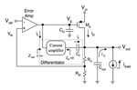
When I simulate DC ( without compensation circuit), results are very good: Vout =1.2V ( Vg=2.7V; Vfb=0.812V)
but when I add compensation circuit, Vout=3.29V (Vg=20mV; Vfeb=2.3V). Because of failure DC bias , I can't test ac response and adjust copensation circuit to suitable.
(As you know, LDO have to the compensation circuit to stability and transient response).
How can I correct it?
I'm looking forward your answer!
Thank you very much!