Continue to Site

Welcome to EDAboard.com

Welcome to our site! EDAboard.com is an international Electronics Discussion Forum focused on EDA software, circuits, schematics, books, theory, papers, asic, pld, 8051, DSP, Network, RF, Analog Design, PCB, Service Manuals... and a whole lot more! To participate you need to register. Registration is free. Click here to register now.

[SOLVED] Problem in FM transmitter

Status
Not open for further replies.

prsarr

Newbie level 3
Joined
Jul 8, 2012
Messages
3
Helped
0
Reputation
0
Reaction score
0
Trophy points
1,281
Activity points
1,310
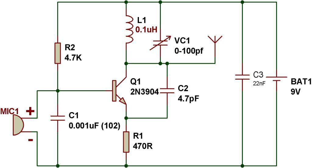
I have made an FM transmitter on a breadboard using a single transistor, BC547... Sometimes I can hear the music on my cell phone at a frequency of 100.35 MHz but mostly its all noisy... What can I do to remove the noise??? I am using a battery of 9V. Will a voltage regulator help in reducing noise?? Also plz tel any precautions to be taken when i build the circuit on a simple circuit booard... Plz help... Thanx
 

FM Transmitter is not realized on breadboards.
You should use PCB-preferable doubl sided-board.Also BC547 is not a good choice for FM transmitter circuit.
Search google ,you'll find many good circuits..

- - - Updated - - -

FM Transmitter is not realized on breadboards.
You should use PCB-preferable doubl sided-board.Also BC547 is not a good choice for FM transmitter circuit.
Search google ,you'll find many good circuits..
 

BF200 / BF494 /2N3866 High Frequency transistors.
 

Hi dear prsarr *

Can you attach your circuit ?
And i think your transistor isn't good .
Best wishes
 

BC547 works fine for low power, one transistor FM transmitters. They can be built on breadboards or veroboard too. I don't think prsarr is looking for state of the art performance - just something simple that works.

Wow, so much negativity on those pages!

The message is clear though:
"Pay 15 dollars for my kit - everybody else's circuit is rubbish (according to me)".

As greentree says; let's see what he's built, then we can make suggestions.
 

Wow, so much negativity on those pages!

And with lots of inteligent stuff like:

" The first item we will look at is the "Q" of the tank circuit. This is a factor known as "Quality" and comes from the fact that an inductor will produce a voltage (of opposite polarity) that can be many times higher than the voltage applied to it. "


And I thought that Q related the stored energy to the dissipated energy in a reactive element... :rolleyes:
 

Thanx all for ur advice... I will change the transistor. I have added an image of the circuit.. Plz suggest any modifications to the circuit to reduce the noise and to increase the range. Will a voltage regulator help to reduce noise??? The antenna I am using is 20 cm long.


- - - Updated - - -

Thanx all for ur advice... I will change the transistor. I have added an image of the circuit.. Plz suggest any modifications to the circuit to reduce the noise and to increase the range. Will a voltage regulator help to reduce noise??? The antenna I am using is 20 cm long.
 

The biggest problem, I think, is frequency stability. Probably your transmitter is detuned easily by body parts or objects nearby. This means that in a given condition your transmitter is broadcasting in a frequency (say, 100.35MHz) and in another conditions it will be broadcasting in another frequency a few MHz away. Probably you can test this with a friend and, preferably, with an "analog tuner" with a conventional dial (rather than the synthesized tuner in your cell phone).

- - - Updated - - -

The biggest problem, I think, is frequency stability. Probably your transmitter is detuned easily by body parts or objects nearby. This means that in a given condition your transmitter is broadcasting in a frequency (say, 100.35MHz) and in another conditions it will be broadcasting in another frequency a few MHz away. Probably you can test this with a friend and, preferably, with an "analog tuner" with a conventional dial (rather than the synthesized tuner in your cell phone).
 

Hi dear
Please test this way , if it worked we talk about reasons !
Do these changes :
22n - 4.7n
4.7p-10p
And put a capacitor before antenna with 10n value .
I hope it be useful for you .

All the best
Green Tree
 

Here is a paper "To Design and Build a Portable, Miniaturized, Multichannel FM transmitter"
It will be useful to those who wants to find out about the theory and how design values are calculated.
You may need some mathematical background to understand some of the reasoning, or you can skip to the final design section.
 

Attachments

  • Design_small_fmtx.pdf
    1 MB · Views: 92

Thanx all of you. I have understood that my design is wrong... I will be changing the design completely
 

Status
Not open for further replies.

Part and Inventory Search

Welcome to EDABoard.com

Sponsor

Back
Top