Continue to Site

Welcome to EDAboard.com

Welcome to our site! EDAboard.com is an international Electronics Discussion Forum focused on EDA software, circuits, schematics, books, theory, papers, asic, pld, 8051, DSP, Network, RF, Analog Design, PCB, Service Manuals... and a whole lot more! To participate you need to register. Registration is free. Click here to register now.

Problem in finding capacitance

Status
Not open for further replies.

Monady

Advanced Member level 4
Joined
Dec 1, 2008
Messages
109
Helped
12
Reputation
24
Reaction score
3
Trophy points
1,298
Activity points
2,151
Hi dear all friends,
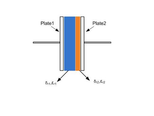
I wanna find value of a capacitor made of two series materials between cap plates. These materials which are used between cap plates have both electrical conductivity and relative permittivity. Since these materials between cap plates have conductivity too, I have no ideal how I can model this capacitor and find its value. I would appreciate it if anybody give me some help.


Tnx for reply,
if each material was a good dielectric, we could do that. but now that each material has conductivity, too, we cannot treat them as series capacitors. For example, assume that the material in the left side (blue one) is a good dielectric with low conductivity and the material in the right side (orange one) has a really good conductivity (but not as good as the cap plate), so what are we supposed to do?
 

You are describing a lossy capacitor, which is no use to man nor beast. Why would you try to find out its value?
 

You are describing a lossy capacitor, which is no use to man nor beast. Why would you try to find out its value?
yeah, you're right. I know that it has no usage. But I'm not the one who write the rules, I'm just expected to find an answer for this question! BTW, do you have any hint about it?
 

... But I'm not the one who write the rules, I'm just expected to find an answer for this question! BTW, do you have any hint about it?
Must admit I never came across a question like this at college, and it's been decades since I had to work out capacitive value from plate area etc.

Sorry, I'm stumped.
 

but now that each material has conductivity, too, we cannot treat them as series capacitors.
It's still a series circuit of complex impedances, that can be calculated. So what's your particular problem with the setup?
 

Last edited:
  • Like
Reactions: Monady

    Monady

    Points: 2
    Helpful Answer Positive Rating
...the material in the right side (orange one) has a really good conductivity (but not as good as the cap plate), so what are we supposed to do?

Perhaps it is better to start finding a good answer for each layer first.
So how could we model a component made by two plates covering a layer of orange material?
 

It's still a series circuit of complex impedances, that can be calculated. So what's your particular problem with the setup?
you say that it's made of two series capacitors that each one has a parallel resistor?

Take a look at equations close to Fig.10 on followiong page, witch covers the issue you´re asking for :
Calculation of electrostatic forces in presence of dielectrics
Tnx for the links. I read them but I think those formulas don't work here. Since materials used between cap plates have conductivity too, and it's not been consideed in those formulas, we cannot find the model by using those equations.
So how could we model a component made by two plates covering a layer of orange material?
dear KerimF, this is exactly my question! If I solve this part of question, solving rest of it will be so easy!
 

you say that it's made of two series capacitors that each one has a parallel resistor?
Yes, i think so. And capacitance and resistance of both "blocks" can be calculated independently by applying simple relations.
C = ε0*εr*F/d
R = d/(F*σ)
 
  • Like
Reactions: Monady

    Monady

    Points: 2
    Helpful Answer Positive Rating
Yes, i think so. And capacitance and resistance of both "blocks" can be calculated independently by applying simple relations.
C = ε0*εr*F/d
R = d/(F*σ)
I'll be so grateful if you could give me any ref about it (if you have).
 

The relations for R and C are directly referring to the defintion of σ and ε, and can be found in many text books. The only point, that's possibly not obvious at first sight, is to treat C and R as independent elements in a parallel circuit. It's however suggested by the definition of complex permittivity. See e.g. Permittivity - Wikipedia, the free encyclopedia
 
  • Like
Reactions: Monady

    Monady

    Points: 2
    Helpful Answer Positive Rating
The relations for R and C are directly referring to the defintion of σ and ε, and can be found in many text books.
I think we cannot use those formulas for finding capacitance and resistance. I read the link you posted and I also took a look at these two pages:
Complex Dielectric Permittivity!!!
Loss tangent - Wikipedia, the free encyclopedia
It seems (as suggested by Gokul43201, in the first link in the post#7) the equivalent circuit would be a series RC circuit. I wrote all relations again myself and found the capacitance value, and its value is:

σ(ω) is the conductivity of the material used as dielectric.
Now really I get confused! This is not what I expected to find! I looked it up in many books, but unfortunately I couldn't find any formula like this, for real capacitors. I expected to have, at least, an ideal capacitor, which its value is independent of conductivity, in series or parallel with a resistor.
 

Generally, you can use both series and parallel equivalent circuits for lossy capacitors. Which one is more suitable mainly depends on the frequency characteristic. But you explicitely stated resistivity and permittivity parameters, which implicitely involves that there's no further frequency dependancy. In other words, there's exactly one resistor and one parallel capacitor in the equivalent circuit.

As a hint, the question parallel or series circuit can be easily anwered by looking at the cases f -> 0 and f -> ∞. Only a parallel circuit can expose the expected behaviour.

P.S.: I presume, that series circuit doesn't mean the obvious fact, that the complete circuit is comprised of two series connected RC parallel circuits...
 
Last edited:

But you explicitely stated resistivity and permittivity parameters, which implicitely involves that there's no further frequency dependancy. In other words, there's exactly one resistor and one parallel capacitor in the equivalent circuit.
I don't get it! why there is not frequency dependency? As I wrote in the former post, the conductivity is a frequency dependent value (σ(ω)).
f -> 0 and f -> ∞
what does f stand for? frequency?
And my question is not about selecting between parallel and series circuits, I have a problem with the value of capacitance in the equivalent circuit. It doesn't make any sense for me that capacitance value is a function of conductivity.
Ps.:yeah, I'm only taking about equivalent circuit of one capacitor made of only one dielectric, not whole circuit.
 

Just an idea, if we have a loop formed by an ideal capacitor C and its two electrodes are connected by an ideal conductor. The equivalent capacitor around the loop is C which means that the part of the loop formed by the conductor has a capcitance = ∞ . This is a starting to point for saying that a capacitance value is a function of conductivity :wink:
 

I don't get it! why there is not frequency dependency? As I wrote in the former post, the conductivity is a frequency dependent value (σ(ω)).
It's the first time, that you mention frequency dependancy in this thread! In this case, it would be good, if you can be more specific about what you want to achieve. If other threads of yours are necessary to understand your intention, please post a link.

P.S.:
It doesn't make any sense for me that capacitance value is a function of conductivity.
In a parallel RC circuit, capacitance won't depend on conductivity, I think, Where did you get it would?

If you prefer a series equivalent circuit for some reason, then you get equivalent series R and C values that both depend on σ and ε. But why should you?
 
Last edited:

In the post #14 I shared a link that describes complex permittivity:
Complex Dielectric Permittivity!!!
In the above link, in the post#7, author wrote:
Write the Capacitance (C) using the complex dielectric function ϵ=ϵ1−iϵ2, and then calculate the capacitive impedance Zc=1/(iωC). You'll see that the impedance turns out to be not purely reactive - there's a resisitive term as well. It is this resistance that dissipates power. The ratio of the resistive component to the reactive component (or real to imaginary terms) is called the loss tangent.
I did what he said, and I found the value of the capacitance (please take a look at the post#14). Do you think that I made a mistake in this way?

and about difference between parallel or series equivalent circuit, I think if you want to use parallel circuit, you should only use Xc (as opposed to the C in series equivalent circuit) in parallel with resistor. Take a look at the "Equivalent circuit" of this link:
Capacitor - Wikipedia, the free encyclopedia
 
Last edited:

I did what he said, and I found the value of the capacitance
Which capacitance? Generally, it's a complex impedance. You can represent it by different equivalent circuits. If you choose a series (ESR + ideal cap) circuit, than the originally parallel circuit parameters have to be transformed. But you didn't yet tell a reason, why one of both representations should be preferred. I suggested the parallel one, because it corresponds to your original problem formulation (σ and ε given).

P.S.:
I think if you want to use parallel circuit, you should only use Xc (as opposed to the C in series equivalent circuit) in parallel with resistor.

The problem is apparently, that you still don't understand the implications of specifying both σ and ε as primary parameters of the lossy capacitor. Physically, you apply an AC voltage to the capacitor and get two current components representing σ and ε respectively. Both can be added to a total current. This ist just another word for a parallel circuit.
 
Last edited:

Status
Not open for further replies.

Similar threads

Part and Inventory Search

Welcome to EDABoard.com

Sponsor

Back
Top