Continue to Site

Welcome to EDAboard.com

Welcome to our site! EDAboard.com is an international Electronics Discussion Forum focused on EDA software, circuits, schematics, books, theory, papers, asic, pld, 8051, DSP, Network, RF, Analog Design, PCB, Service Manuals... and a whole lot more! To participate you need to register. Registration is free. Click here to register now.

Problem in choosing the right sensor

Status
Not open for further replies.

umery2k75

Advanced Member level 1
Joined
Apr 19, 2006
Messages
434
Helped
41
Reputation
80
Reaction score
15
Trophy points
1,298
Location
Pakistan
Activity points
5,748
lm2907 response time

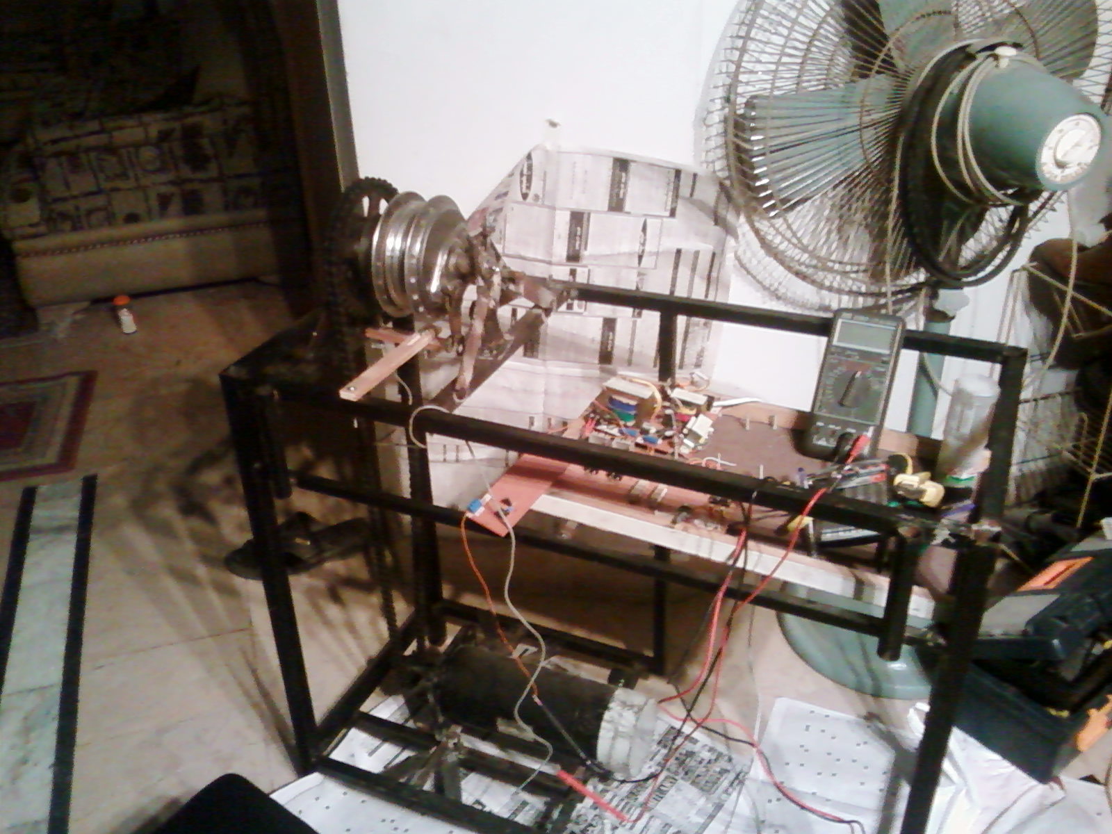
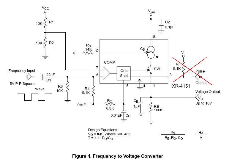
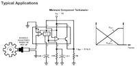
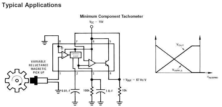
This is the circuit, which I have made for frequency to voltage converter.I'm using this to measure the speed of the DC motor.I am using LM2907 frequency to voltage converter IC.


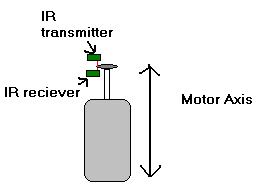
So, after making this circuit, then next thing to do was to find the sensor, then I went to market and bought magnetic sensor.This is the magnetic sensor, the other part was also same like this.


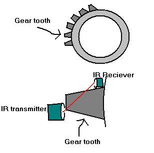
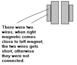
The functioning of this magnetic was something like this.

69_1205440506.jpg


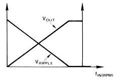
Then I start the motor and started increasing the speed of it, I was expecting a linear increase in voltage, or in otherwords I was expecting this curve output.

57_1205440702.jpg


but I didn't get it.So I realize what could be wrong with my sensor, so at the end I realize it was basically a magnetic door sensor, which I bought from the market.I should have some another sensor, then I removed that sensor from my circuit.

I went to the market again to look for right sensor, that looks similar to this one as given on datasheet.

30_1205440899.jpg


then I found a shop where, these kinds of sensor were available and were of many sizes, they were named as Proximity sensor in that shop.Although in Datasheet the name of sensor is written as "Variable Reluctance Magnetic Pickup".Although one day before this day,I had gone to the market and had asked for "Variable Relucatnce Magnetic Pickup", but nobody knew to what I was asking for, so I couldn't get that sensor on that day.
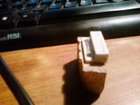
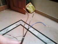
So I bought one proximity sensor and attached to the mechanical assembly of my project.Like this


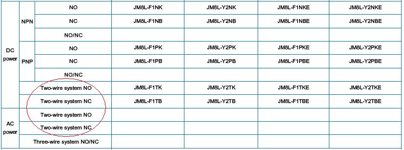
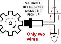
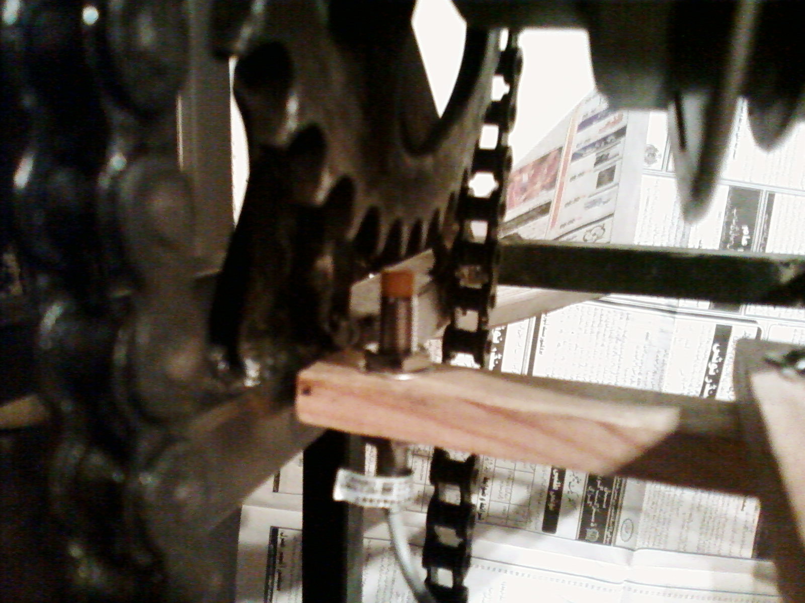
when I was to attach the sensor wires to my circuit.I realized that there were three wires coming from the sensor!


In the datasheet, sensor has only two wires.

33_1205442899.jpg


In datasheet of LM2907 it's not clearly written what kind of sensor is to be used.I'm not still sure whether I need to use proximity sensor or not.I had bought the proximity sensor, because it was the only sensor in the market that resembles the most as given on datasheet.I had spent several hours in market looking for the sensor that looks exactly the same as given in datasheet.

Things I need to confirm about this:

A)Do you think Variable Reluctance Magnetic Pickup as mentioned on Datasheet is also called as Proximity sensor?

B)Secondly, I want to know if I had bought the correct sensor(proximity sensor), so why my sensor has 3 wires, it should have two wires like the one shown in datasheet.

Project:
 

You need to check the proximity sensor datasheet.
For example some details about different sensors here:
http://www.am.pepperl-fuchs.com/pdf/documents/sc08_80-82_3-6_5mm_3-wire_dc_inductive.pdf

This means your sensor need to be connected to a power supply in order to obtain output pulses.

http://www.emesys.com/pdfs/parts/LM2907.pdf

The LM2907 series of tachometer circuits is designed for
minimum external part count applications and maximum versatility.
In order to fully exploit its features and advantages
let’s examine its theory of operation. The first stage of operation
is a differential amplifier driving a positive feedback
flip-flop circuit. The input threshold voltage is the amount of
differential input voltage at which the output of this stage
changes state.


But maybe this is not enough for the sensor you have. What’s the exact version of the IC used?

Two options (LM2907-8, LM2917-8) have
one input internally grounded so that an input signal must
swing above and below ground and exceed the input thresholds
to produce an output. This is offered specifically for
magnetic variable reluctance pickups which typically provide
a single-ended ac output


The differential input options (LM2907, LM2917) give the
user the option of setting his own input switching level and
still have the hysteresis around that level for excellent noise
rejection in any application. Of course in order to allow the
inputs to attain common-mode voltages above ground, input
protection is removed and neither input should be taken
outside the limits of the supply voltage being used. It is very
important that an input not go below ground without some
resistance in its lead to limit the current that will then flow in
the epi-substrate diode.

An idea of schematics for the differential input LM2907 is attached
 

    umery2k75

    Points: 2
    Helpful Answer Positive Rating
I have LM2907N-8 IC, in which one input is grounded.It's 8 pin IC.
Do proximity sensors comes in 2 wires and 3 wire output? Have a look at this.I found some manufacturer's datasheet.


It's URL is:
**broken link removed**

If I make this circuit


Can I still use the 3-wire proximity sensor or do I have to use the 2-wire proximity sensor?
 

The sensor used for that schematics it's a passive one, like a simple coil.
It’s more similar to an audio head in tape recorders. The output signal is ac voltage like a double spike symmetric signal crossing to zero. In that case you need to adapt the input to accommodate a large signal. I don’t know if the circuit will accept this signal, so you need to try. :D
 

    umery2k75

    Points: 2
    Helpful Answer Positive Rating
Just came back from the market, I couldn't find the two wire sensor.The sensor that I found of two wires were AC and were very big and has head size of around 20mm in diameter.I want 8mm dia. The shop keeper told me that 2 wires proximity sensors are used as a switch and has load connected in it's series, he further more added that you'll only find 3 wire proximity sensor in smaller size, anywayz I showed datasheet to him.He told me that maybe that manufacturer didn't show the 3 wires, because 1 wire was of power and other two wires,the manufacturer had shown as how proximity sensor is to be attached.He told me proximity sensor needs power to operate.If you connect proximity sensor with two wires it will not get power.He added that, maybe in datasheet the power wire of proximity sensor is omitted.
Anywayz I have purchased some more components for another frequency to voltage converter, it's based on 4151.It accepts the square wave as input and converts into linear voltage through op-amp(as integrator).So that if LM2907 frequency-to-voltage converter circuit doesn't work.I'll make the another type of frequency-to-voltage circuit.

I think the best way to check is to give the sine wave input to LM2907 through function generator and to see it it works on Sine wave or not.

and secondly I must check the output of proximity sensor on Oscilloscope, as what kind of output is given to me.Once I know as what kind of output I get, I'll then make the frequency to voltage converter.

I think I get into problem, may be because my approach was not correct! I must first check the availability of sensors, then accrodingly I must make my frequency to voltage circuit, where as what I had done.I had first made the circuit, then I searched for the sensor and unfortunaltely I didn't get the required sensor for my circuit.

Whats your say on that?
 

Your basically visited the wrong market, or may be, the type of sensor National intended for LM2907 isn't manufatured as at standard part at all. The IC is a building block for a simple rotation speed sensor, and they apparently think that a designer should know how to manufacture a suitable sensor. Most professional designers would actually know, I think.

The suggestions to adapt the industrial proximity sensors to LM2907 may possibly work, I would use a simple electromagnetic sensor as intended by National. Mister_rf was almost right about the construction of the sensor. He forgot however an important detail: It must utilize a permanent magnet to generate a voltage with variation of reluctance, in other words, when a ferromagnetic material is approaching and departing the sensor. Thus the most simple construction is a cylindrical magnet with a coil around it.
 

    umery2k75

    Points: 2
    Helpful Answer Positive Rating
As you have written that, a simple electromagnetic sensor can be made by using a cylindrical magnet with fine wire wound across it.If I make this sensor and by helding the sensor in my hand, if I move the sensor on top of gear teeth will the sensor generate some voltages on the coil? the sensor is not attached to anything, it's in my hand.
 

Yes, but the voltage is very low.
Initially I was suggesting to improvise and use an audio head instead an pickup coil , due to natural magnetism of ferromagnetic gear teeth… :D
The only problems is related to the small distance between head and gear teeth.

Now you can try to use this active 3 wire sensor with LM2907 but you need to test if the output signal on low voltage level is acceptable by the circuit to be considered as crossing to zero.
Maybe you want to consider to manufacture a small passive pickup coil based on the FvM idea.
 

The voltage is very low per turn, thus you probably need many thousand turns for the coil. Also the voltage ist speed dependant, cause it senses the variation speed of magnetic field. But this type of sensor generally has been used in dirty enviroment, e. g. with electronic ignition systems. A magnetic "conclusion", e. g. an "U" surrounding the coil can increase the sensitivity.

To be true, I almost used optical sensors for speed and position detection in instruments, either transmissive or reflective. There are very small and much easier to handle, at least in a clean enviroment.
 

I had done few changes to my sensor circuit.
I had changed the frequency to voltage converter circuit.Now I'm using XR-4151 as F/V converter.It accepts the square wave input.My sensor also gives the square wave ouput, so it's a perfect match.
The square wave output is 5V peak-to-peak, as it should be accroding to the datasheet.


I'm having problem now.The proximity sensor can't count teeth of gear more than 490 times a second.After crossing this limit I start getting wrong results.In my machine I have two gears, the upper gear consist of 41 teeths and lower gear consists of 14 teeth.Initially I had my sensor installed on upper gear.So I remove the sensor and installed on the lower gear with 14 teeth.So frequency has automatically been reduced to a factor of 41/14=2.92
Anywayz.The space between the sensor and gear teeth is very close that a piece of paper can pass through it and if paper is folded twice or three time it can hardly pass between the sensor and teeth gear.

What should I do now? my sensor isn't working at full speed, it only works for the 3/4th of the top speed and after that it no longer work.What all I want is to measure the RPM of the motor at which it's been driven.

I think the options now I have are:

a)Buy another motor which has built-in tachogenerator.
b)Buy tachogenerator seperately.


Option (a) and (b) will work for sure, but that would be expensive.

c)Buy another proximity sensor

I don't know whether buying a new proximity sensor would work or not.Whether it can count teeths at high speed or not.I'm afraid that this option could result in loss of time,effort and money.

d)Build a sensor

I can build two kinds of sensors, I will try to make the Proximity sensor, as FvM told me about.Furthermore I'll do more research on it as how to make it.Secondly I can make a infra red based sensor system,ofcourse I don't have to make the IR led.The system would consists of a disc with a hole, sensor and reciever will be on two sides of the disc.

Making a sensor and using a sensor are two sides of the coin.I can't gurantee that the sensor I will make will work accurately or not.This could result in a wastage of time,effort and money from the project point of view, because what ever a person do, it learns from what he/she do, I can learn how to make a good and accurate sensor from this.But I think that I will not be able to focus on DC motor speed controller project.I'll get diverted.


Your opinion is needed?


Have you measured the input signal on pin 6 or on the output pin 3?
Maybe it’s a limitation in the sensor, anyway 490Hz it’s like 29400 rpm.
One suggestion is to change and increase the R4 value up to 6.8-8.2K.

Another one: if it’s possible to change the position of the sensor and to adapt the spokes to trigger so you’ll have less pulses per minute.

And finally change to optical... :D
 

The problem with proximity sensors is, that they have an oscillator with finite start-up time. Thus they have a response time respectively maximum switching frequency, usually specified with the sensor. Common industrial inductive proximity switches have 500 Hz - 1 kHz maximum switching frequency. That means, the gear wheel teeth count must be limited according to maximum rotation speed.

I still think, that a photointerrupter would be the most easy solution. It can probably utilize the gear wheel intended for inductive sensor. Even a customer of mine, who is a mechanician rather than an electronic engineer is able to design photointerrupter constructions for his instruments, just using an IR-LED and a phototransistor from a catalog distributor.

anyway 490Hz it’s like 29400 rpm
Would be with one teeth, but 2450 with the 12 teeth gear wheel you showed!
 

When I measured the frequency response of the sensor.It wasn't attact to the XR-4151 circuit.It was attach to nothing.The oscilloscope was giving the values directly.So changing the values of resistance in the circuit doesn't matter.The circuit wasn't attach to sensor.

Another one: if it’s possible to change the position of the sensor and to adapt the spokes to trigger so you’ll have less pulses per minute.

It's a good idea, but I think that the square wave I get will not have 50% duty cycle.It will have less ON time and more OFF time.I don't know whether the XR-4151 frequency to voltage converter would accept the square wave of variable duty cycle.I have to see this.

I have two gears, one has spokes and other just don't.Right now I have installed my sensor on the gear where there are no spokes.Prior to this one, my sensor was attach to the gear where there were spokes.Yes, I can shift it to upper side.

Added after 1 minutes:

Added after 12 minutes:

I still think, that a photointerrupter would be the most easy solution

I have made this diagram,I have understand this in that way.Do I have to make photointerrupter in this way? The ON will be represented when a beam can pass between the gear wheel.The OFF would be represented when a beam cannot pass between the gear wheel(because a tooth would be blocking the beam).


40_1206268861.jpg
 

The ON will be represented when a beam can pass between the gear wheel.The OFF would be represented when a beam cannot pass between the gear wheel(because a tooth would be blocking the beam).
Basically yes, but the optical beam should be in parallel to motor axis. Don't know about the thickness of your gear wheel? IR-LED/phototransistor could be used with a few cm distance at maximum without optics, also a tube to shield enviromental light may be necessary at the phototransistor. You can also use visible red LED, but IR would giver higher response. Notice that LED and phototransistors are available with different optical half angles. Low half angle should be preferred.
 

    umery2k75

    Points: 2
    Helpful Answer Positive Rating
Yes. For a thin gear wheel or a shutter, you could use "side view" sensor. For longer distance, 5 mm (T1 3/4) case would be optimal because of the higher directivity. IR LED used in remore controls have e. g. small half angle.
 

Off topic
FvM said:
...
anyway 490Hz it’s like 29400 rpm
Would be with one teeth, but 2450 with the 12 teeth gear wheel you showed!
The picture attached it's only to understand the position of the sensor.
That’s the first one gear picture quickly founded on the net… :D
 

The picture attached it's only to understand the position of the sensor.
I see.

Actually, it would be possible to use a one "tooth" (or better two teeth to avoid unbalanced mass) "gear wheel" or shutter. On the other hand, a higher pulse frequency would be preferred to reduce control loop dead-time and simplify the filtering in f/U conversion. Thus a 0.5 or 1 kHz limited sensor may be unsuitable for speed control, depending on the controller specification (almost unknown to me).
 

And if the pulses must be 50% duty cycle, you can use a D flip-flop in between, so that it "captures" the signal at the moment the clock goes high, and subsequent changes of the data line do not influence Q until the next rising clock edge.
 

Status
Not open for further replies.

Similar threads

Part and Inventory Search

Welcome to EDABoard.com

Sponsor

Back
Top