Continue to Site

Welcome to EDAboard.com

Welcome to our site! EDAboard.com is an international Electronics Discussion Forum focused on EDA software, circuits, schematics, books, theory, papers, asic, pld, 8051, DSP, Network, RF, Analog Design, PCB, Service Manuals... and a whole lot more! To participate you need to register. Registration is free. Click here to register now.

Problem in an ECG circuit

Status
Not open for further replies.

bour1992

Newbie level 3
Joined
Sep 12, 2011
Messages
4
Helped
0
Reputation
0
Reaction score
0
Trophy points
1,281
Activity points
1,314
Hello, I am trying to make a simple ecg/emg acquisition circuit.

I am using 2 of these

https://www.olimex.com/Products/EEG/Electrodes/EEG-AE/

active electrodes for the differential signal and this

https://www.olimex.com/Products/EEG/Electrodes/EEG-PE/

as a passive DRL electrode.

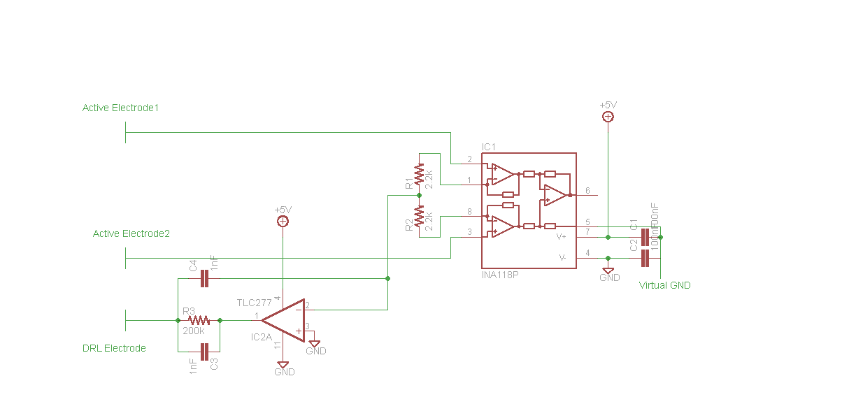
My supply is the 5V output of a LM7805 and I create a virtual ground at 2.5V using the TLE2426.

This


is what I have built in a breadborad.

I connect the output of the INA118 to an oscilloscope but nothing usefull is shown.

Do you see anything wrong in it?
 
Last edited by a moderator:

Is it biased ok at least?
DRL output is OK?

Note all DC input voltages vs CM limits

I didn't measure the DRL output. I will do it the next time I touch the circuit.
What do you mean about the bias and DC input voltages vs CM limits?
 

Hi,

i see the problem in th DRL circuit.

If you want to generate 2.5V, then use a 1:1 voltage divider from 5V and feed it to in+ of OPAMP.
Connect OPAMP output to IN-.
Maybe you can use "virtual ground"

Your DRL circuit with C4 connected to R1/R2 will influence ECG signal.

****

If you want to build an active voltage generator, then don´t use the high ohmic IN- inputs of the INA. Use the outputs instead.


Klaus
 

I didn't measure the DRL output. I will do it the next time I touch the circuit.
What do you mean about the bias and DC input voltages vs CM limits?

Next time you design/debug anything, check the DC voltages for each pin for abnormal level and report it.

The concept of DRL is to have the buffered CM signal to neutralize noise.

Does your DRL signal do this? It seems to integrate DC error relative to 0V rather than V/2 , with an AC unity gain
 

The instrumentation amplifier is supposed to have its inputs biased at half the supply voltage or at 0V when using a dual polarity supply. Your inputs are not biased.
The opamp picks up the common mode signal (electrical hum) picked up by both electrodes and is fed out-of-phase to the patient's leg to cancel the hum.

Here is an ECG circuit that uses a dual-polarity supply:
 

Attachments

  • ECG-3.PNG
    ECG-3.PNG
    22.8 KB · Views: 124

The instrumentation amplifier is supposed to have its inputs biased at half the supply voltage or at 0V when using a dual polarity supply. Your inputs are not biased.
The opamp picks up the common mode signal (electrical hum) picked up by both electrodes and is fed out-of-phase to the patient's leg to cancel the hum.

Here is an ECG circuit that uses a dual-polarity supply:

What should I do to bias the inputs?
A resistor between each of them and virtual ground?

I can't see the bias in the ECG circuit you posted.
 
Last edited:

What should I do to bias the inputs?
A resistor between each of them and virtual ground?

I can't see the bias in the ECG circuit you posted.

Keep in mind for any Op Amp to be linear the inputs must be at the same voltage and that voltage MUST be within the linear input range of the IC. Some can go to both rails, but not both your IC's

INA spec's
Linear Input Voltage Range
(V+) – 1 to (V+) – 0.65 upper limits
(V–) + 1.1 to (V–) + 0.95 lower limits

Note your design with TLC277 (+in) is grounded with a single supply.
That only works with a split supply , same as audioguru's example.

Therefore change gnd to V/2 for +in on DRL amp (pin3)

This is what I mean by check Vdc and CM range.
 

Your original schematic "says" virtual ground but does not have a virtual ground (half the supply voltage).
 

You do not need a TLE2426 "rail splitter" IC that has an output current as high as 20mA because the load in your circuit at half the supply voltage is almost no current. Wwo resistors and a capacitor will replace it.
 

Thanks to all of you for your suggestions. I took them into account and learned some usefull things about in-amps.
Seems like the problem was with the active electrodes. I replaced them with some wet electrodes and the signal seems fine now.
 

Status
Not open for further replies.

Similar threads

Part and Inventory Search

Welcome to EDABoard.com

Sponsor

Back
Top