RDL
Newbie level 3

- Joined
- Feb 21, 2015
- Messages
- 4
- Helped
- 0
- Reputation
- 0
- Reaction score
- 0
- Trophy points
- 1
- Location
- Edmonton, Canada
- Activity points
- 26
Further to the old discussion on https://www.edaboard.com/threads/298751/
I tried to use the first circuit illustrated. I have modified the drawing to illustrate the pins used and to show 9 Volts IN.

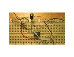
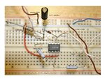
A 40 KHz signal input is giving no output, on the scope, which indicates a screw-up. Also attached is a photo of the breadboard to give you a better understanding of my problem. It may appear that the bottom 10K Resistor is in the wrong hole but the lead does bend inwards to connect with the Input which then leads to #2 of the CA3140.

After the laughter ceases is it possible to find out what is wrong or what I should measure?
Raymond
I tried to use the first circuit illustrated. I have modified the drawing to illustrate the pins used and to show 9 Volts IN.

A 40 KHz signal input is giving no output, on the scope, which indicates a screw-up. Also attached is a photo of the breadboard to give you a better understanding of my problem. It may appear that the bottom 10K Resistor is in the wrong hole but the lead does bend inwards to connect with the Input which then leads to #2 of the CA3140.

After the laughter ceases is it possible to find out what is wrong or what I should measure?
Raymond


