Continue to Site

Welcome to EDAboard.com

Welcome to our site! EDAboard.com is an international Electronics Discussion Forum focused on EDA software, circuits, schematics, books, theory, papers, asic, pld, 8051, DSP, Network, RF, Analog Design, PCB, Service Manuals... and a whole lot more! To participate you need to register. Registration is free. Click here to register now.

Problem at op amp shematic orcad

Status
Not open for further replies.

Tom2

Full Member level 5
Joined
Nov 11, 2006
Messages
318
Helped
3
Reputation
6
Reaction score
3
Trophy points
1,298
Activity points
3,457
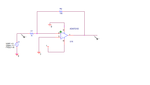
I tried to build a simple inverting amplifier in orcad as present in the figure bellow.The problem appear when i tried to simulate the circuit.
the error in capture is :

WARNING: [NET0093]
No PSpiceTemplate for U1A, ignoring


and at the ps spice :
ERROR -- Less than 2 connections at node N15618


Is anyone who know what is the problem and how to fix it ????????????????????????????


Thanks in advance.
 

Attachments

  • opamp_problem.png
    opamp_problem.png
    11.7 KB · Views: 74

Select components from the simulation library that have SPICE models.
 

As FvM noted the model you have used in the design is missing the PSpice Template which is required for simulation.

When performing a Part Search or adding an additional library ensure the search path is set for the PSpice library:

C:\CADENCE\SPB_16.3\TOOLS\CAPTURE\library\pspice

It should also be noted the green circle next to the component indicates the lack of a PSpice Template as well.

BigDog
 
  • Like
Reactions: Tom2 and FvM

    FvM

    Points: 2
    Helpful Answer Positive Rating

    Tom2

    Points: 2
    Helpful Answer Positive Rating
Your Bias voltage to the + input should be Vin/2 not ground if using a single ended supply as shown.
If you use the circuit as shown you will only get 1/2 waveform out.
either change the bias voltage or use a +v and -V supply.
 

I solved the problem and now i find a new problem. I try to simulate an AC sweep (frequency respond) in orcad (with the above circuit). The problem is that i can see any graph. The graph is present only the axis (empty graph).
 

Attachments

  • freq..png
    freq..png
    8.3 KB · Views: 59
  • graph.png
    graph.png
    13.3 KB · Views: 61

You need to specify a trace/output point.

Either place a Net Alias, for example "out" and then add the Trace to the plot by utilizing the "Add Traces" window with the expression "V(out)".

Or place a Marker at the point of interest, which can be found at the PSpice->Markers menu and then rerun the simulation.

PSpiceSim.jpg


BigDog
 

And how to convert the schematic and the graph to pdf ????
 

I have Adobe Acrobat Professional installed on all my systems, therefore I not sure if the capability to print to an Adobe PDF is possible with your current system. I use this technique to to convert both the schematic and plots to PDFs. You can also use a utility like PicPick to grab a screen shot of either image. There maybe other techniques available as well.

BigDog
 

You can also export the schematic to pdf using Capture> Pdf export utility. Refer tcl Application guide for details. This is available <installdir>\tools\capture\tclscripts\OrCAD_Capture_TclTk_Extensions.pdf
 

If i would like to built a circuit in which there are micro-controllers/fpga... Is it possible to simulate their output result of the micro-controller/fpga?? if yes how is this possible?
 

Status
Not open for further replies.

Similar threads

Part and Inventory Search

Welcome to EDABoard.com

Sponsor

Back
Top