pkl520
Newbie level 1
hello i'm new here and a beginner in verilog
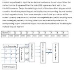
i have problem about scanning 3x4 keypad in verilog

above is question
now i already have 4-2 priority encoder to put row&column into keypad scanning and then
put data into binary to bcd converter
but now i'm stuck here. because i dont know how to put data into binary to bcd converter
can some give a help or hint?
i will be apreciate.
p.s: the attachment is my verilog code
i have problem about scanning 3x4 keypad in verilog

above is question
now i already have 4-2 priority encoder to put row&column into keypad scanning and then
put data into binary to bcd converter
but now i'm stuck here. because i dont know how to put data into binary to bcd converter
can some give a help or hint?
i will be apreciate.
p.s: the attachment is my verilog code
Code:
module prio_encoder4_2 ( d0,d1,d2,d3 ,x ,y );
input d0 ;
input d1 ;
input d2 ;
input d3 ;
output reg  x ;
output reg  y ;


always @ (d0 or d1 or d2 or d3)
  if (d3 == 1)
  {x,y} = 3'b11 ;
else if (d2 == 1)
  {x,y} = 3'b10 ;
else if (d1 == 1)
  {x,y} = 3'b01 ;
else if (d0 == 1)
  {x,y} = 3'b00 ;
else
  {x,y} = 3'bxx ;

endmodule

module matrix_scan(co1,row,a1,b1,c1,d1);//a1~d1 is output

input [3:0] co1;
input [3:0] row;
output a1;
output b1;
output c1;
output d1;
prio_encoder4_2 en1(.d0(co1[0]) ,.d1(co1[1]) ,.d2(co1[2]) ,.d3(co1[3]) ,.x(a1) ,.y(b1) );
prio_encoder4_2 en2(.d0(row[0]) ,.d1(row[1]) ,.d2(row[2]) ,.d3(row[3]) ,.x(c1) ,.y(d1) );

endmodule

module add3(in,out);
input [3:0] in;

output [3:0] out;
reg [3:0] out;
matrix_scan aa(.co1(co1),.row(co1),.a(in[0]),.b(in[1]),.c(in[2]),.d(in[3]));//have problem here~!!!
always @ (in)
 case (in)
 4'b0000: out <= 4'b0000;
 4'b0001: out <= 4'b0001;
 4'b0010: out <= 4'b0010;
 4'b0011: out <= 4'b0011;
 4'b0100: out <= 4'b0100;
 4'b0101: out <= 4'b1000;
 4'b0110: out <= 4'b1001;
 4'b0111: out <= 4'b1010;
 4'b1000: out <= 4'b1011;
 4'b1001: out <= 4'b1100;
 default: out <= 4'b0000;
  endcase
endmodule


module seg7 (bcd, leds);
	input [3:0] bcd;
	output [1:7] leds;
	reg [1:7] leds;

	always @(bcd)
		case (bcd)       //abcdefg
			0: leds = 7'b1111110;
	   		1: leds = 7'b0110000;
			2: leds = 7'b1101101;
			3: leds = 7'b1111001;
			4: leds = 7'b0110011;
			5: leds = 7'b1011011;
			6: leds = 7'b1011111;
			7: leds = 7'b1110000;
			8: leds = 7'b1111111;
			9: leds = 7'b1111011;
			default: leds = 7'bx;
		endcase

endmodule