Continue to Site

Welcome to EDAboard.com

Welcome to our site! EDAboard.com is an international Electronics Discussion Forum focused on EDA software, circuits, schematics, books, theory, papers, asic, pld, 8051, DSP, Network, RF, Analog Design, PCB, Service Manuals... and a whole lot more! To participate you need to register. Registration is free. Click here to register now.

Problem about IR2110

Status
Not open for further replies.

Mizan.Bangladesh

Junior Member level 3
Joined
Nov 15, 2012
Messages
25
Helped
0
Reputation
0
Reaction score
0
Trophy points
1,281
Activity points
1,459
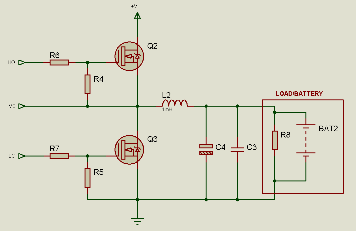
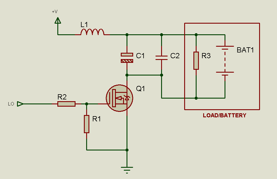
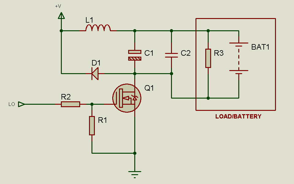
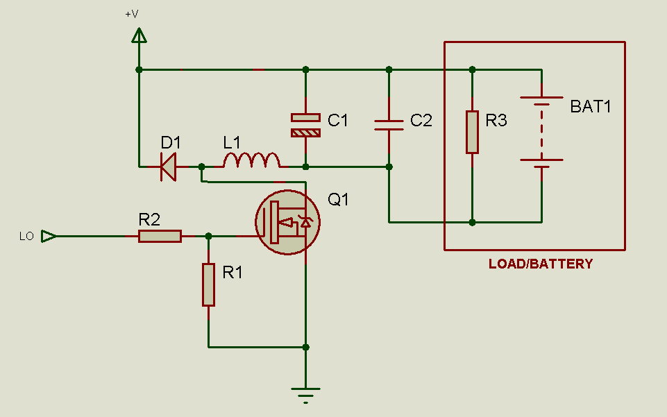
I want to drive a 15V / 20V Source from the mosfet drain with ir2110, My PWM freq=20KHz, i want to vary the voltage from 0 to 15V or 0 to 20V.
Please tell me which side Hin/Lin I have to use.
Also, i want to explain that I will use the output voltage of MOSFET to charge a 12V LED acid Battery with variable supply.

Please Response to me ....!!!
Thanks in Advanced...
 
Last edited:

Since you'll be using the MOSFET as a high-side switch, you need to use the IR2110 as a high-side driver.

So, connect your drive signal to the IR2110 HIN pin. Connect the HO pin to MOSFET gate with a resistor in between. Connect a resistor between MOSFET gate and source. Connect the VS pin to MOSFET source. Connect load between MOSFET source and ground.

Vary the duty cycle to the input to vary output voltage.

If you require a smooth DC output voltage, use an LC filter at the output - an inductor between MOSFET source and load, and a capacitor across the load.

Hope this helps.
Tahmid.
 
Since you'll be using the MOSFET as a high-side switch, you need to use the IR2110 as a high-side driver.
I don't clearly hear "high-side switch" from the post. "drive a Source from the mosfet drain" is at least ambiguous.

In case a high side switch is actually meant, I see a possible problem with the suggested configuration. The IR2110 bootstrap circuit will only work, if the load is periodically shorted to ground. This doesn't necessarily work with all kinds of load, e.g. the mentioned battery.
 
  • Like
Reactions: tpetar

    tpetar

    Points: 2
    Helpful Answer Positive Rating
I don't clearly hear "high-side switch" from the post. "drive a Source from the mosfet drain" is at least ambiguous.

Yes, the OP should clear the doubt.

In case a high side switch is actually meant, I see a possible problem with the suggested configuration. The IR2110 bootstrap circuit will only work, if the load is periodically shorted to ground. This doesn't necessarily work with all kinds of load, e.g. the mentioned battery.

In that case, a low side switch could also be used, which is driven by a signal which is inverse of the high-side drive signal. So, the low-side switch could pull the capacitor -ve to ground and charge the capacitor. That is, of course, if the OP does indeed use high-side switching.
 

I am not clear from your post which side should I use.? Please clear me....

- - - Updated - - -

I am not clear from your post which side should I use.? Please clear me....

Also what is the meaning of ''OP'' ?
 

In your circuit, will the drain of the MOSFET be connected to +ve and the load between source and ground? If so, you have to use high-side.
Or
In your circuit, will the source of the MOSFET be connected to -ve and the load between +ve and drain? If so, you have to use low-side.

OP means original poster, which is you. :smile:
 
In your circuit, will the drain of the MOSFET be connected to +ve and the load between source and ground? If so, you have to use high-side.
Or
In your circuit, will the source of the MOSFET be connected to -ve and the load between +ve and drain? If so, you have to use low-side.

:

I want to remind you that,
I want to vary a 20V Supply from 0V to 20V with ir2110.
Please tell me which side(Hin/Lin) should I use from your experience. My PWM freq=20KHz.
Also, i want to explain that I will use the variable supply voltage to charge a 12V LED acid Battery.

So, Which Side should I use & why, Please Clear me..
 

You can use one of the two configurations:

4408248800_1353227877.png


1265408200_1353227877.png


As you can see, the low side configuration (the bottom one) will require less parts. However, in this configuration there is no common ground with the load. For the high side configuration (the top one), while there are more parts, you have the advantage of common ground (if you need it).

Hope this helps.
Tahmid.
 
As shown, the second circuit dumps the inductor's stored energy to the transistor, forcing it into avanlanche breakdown and possibly exeeding it's maximum ratings. The circuit efficiency isn't better than a linear regulator in this case. It should be supplemented by a diode between drain and V+ to a buck converter. The inductor can be also placed between drain and battery-, reducing output PWM noise.
 
As shown, the second circuit dumps the inductor's stored energy to the transistor, forcing it into avanlanche breakdown and possibly exeeding it's maximum ratings. The circuit efficiency isn't better than a linear regulator in this case. It should be supplemented by a diode between drain and V+ to a buck converter.

3944351200_1353230163.png


The inductor can be also placed between drain and battery-, reducing output PWM noise.

Could you please explain this?
 
I thought about this modification. It's electrical equivalent, except for battery+ directly connected to V+. The battery circuit doesn't swing at PWM frequency, potentially radiating interferences. Basically I'm going back to a standard buck converter, with V+ and V- exchanged.

8518946900_1353231188.png
 
Thanks to all
For giving me a clear concept. I want to implement it in Hardware.
But what should be the values of
1. Inductors, 1mH..?
2. Capacitors..?
3. Capacitor C2 is ceramic but capacitor C1 is what type..?
4. MOSFET Series name which will be efficient..?
5. Resistance values..?
6. Diode, 1N4007..?
7. Also to drive high side what should be the value of capacitor between VB & VS..?
8. Here do I need any Zener Diode..?
9. Finally any Extra circuit Element Do i need to Drive MOSFET with IR2110..?


If you show these value with circuit diagram that should be more better for me.

Please help me. Perhaps, You are in Pressure for me..???
 

1), 2) The values of the inductor and capacitor will depend on the switching frequency you use.
3) C1 is an electrolytic capacitor.
4) Depends on your current requirement. Take a look at STP55NF06, IRFZ44N and IRF3205. These are easily available in the local market and are quite cheap.
5) R1: 1k to 4.7k. R2: 10R should be okay.
6) No. Schottky (better) or ultrafast type. Choose one that can handle the required current.
7) Depends on frequency and duty cycle.
8) Not required, but you can use one between gate and source if you wish.
9) Drive this MOSFET from the IR2110. Use sufficient filtering and decoupling.

Hope this helps.
Tahmid.
 
Thanks Tahmid Brother for your quick support..!!!
I am using 20kHz and 18 to 25V in +v.

So, what is the answer of no.
2. ?
4. i am looking
6. diode number..?
7. 20kHz & Duty cycle will vary from 0-100%, so what is capacitor value
9. Please clear me about sufficient filtering & Decoupling?
10. need any extra capacitor for LO side..???

It will be too much helpful for me...!!!
 

1), 2) For calculation of inductance and capacitance, you can use this: **broken link removed**
Use values larger than calculated.

6) What is your current requirement?
7) If you're using low side drive, these aren't required, since these are required only for high-side drive.
9) Connect a 0.1uF ceramic capacitor in parallel with 22uF electrolytic capacitor between VDD and ground, and between VCC and ground.
10) The capacitors between VCC and ground as mentioned in point 9.

Hope this helps.
Tahmid.
 
Thanks a lot for your response....!!!!

6. You used a D1 diode in the figure, I want to know what should be the diode number..?
7. In case of High side drive what should be the value of Capacitors.

Please response to me..?
 

6) Well, like I said before, it depends on the current capacity. What is the maximum current the load will draw? As for the type of diode, you need to use an ultrafast diode. You could use a schottky rectiifer.
7) You should remember that you can't use 100% duty cycle (or high duty cycles near 100%) as the bootstrap capacitor needs sufficient time to charge. You can try with 100uF and see. If it's insufficient, you may want to move up to 220uF. Keep in mind the maximum duty cycle. Connect a 0.1uF ceramic capacitor in parallel to the bulk capacitor.

Hope this helps.
Tahmid.
 
Keep in mind the maximum duty cycle. Connect a 0.1uF ceramic capacitor in parallel to the bulk capacitor.


why i have to Connect a 0.1uF ceramic capacitor in parallel to the bulk capacitor.??
Please clear me .
thanks
 

Keep in mind the maximum duty cycle. Connect a 0.1uF ceramic capacitor in parallel to the bulk capacitor.

why i have to Connect a 0.1uF ceramic capacitor in parallel to the bulk capacitor.??
Please clear me .
thanks
 

You can use one of the two configurations:

4408248800_1353227877.png


1265408200_1353227877.png


As you can see, the low side configuration (the bottom one) will require less parts. However, in this configuration there is no common ground with the load. For the high side configuration (the top one), while there are more parts, you have the advantage of common ground (if you need it).

Hope this helps.
Tahmid.


In case of first circuit i.e. high side HO & LO the two inputs should become opposite input? how can i do that?
Please answer me.
I need to know it please.
 

Status
Not open for further replies.

Similar threads

Part and Inventory Search

Welcome to EDABoard.com

Sponsor

Back
Top