Chest
Member level 3
Hi there,
I'm using IE3D to do simulation in rectangular patch antenna. I'm faced some problem which is modelling of an probe-fed patch antenna with infinite ground plane. I'm cannot place the feed point to the patch. And i'm checked the IE3D manual that have not this example, only infinite ground. So below is my results and manual example. Please, anyone can help me to figure out my mistake.
Thanks in advance.
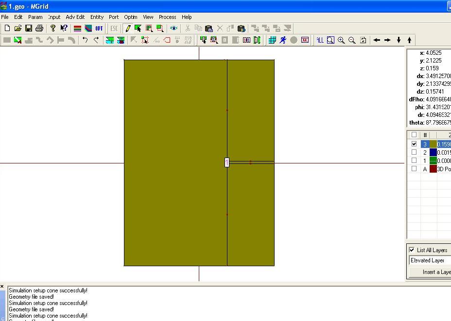
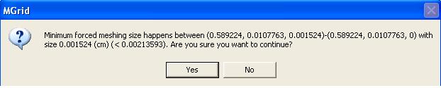
simulation result
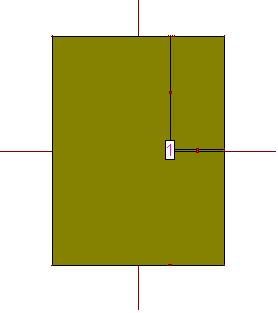
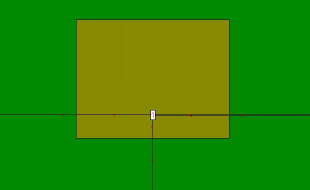
IE3D manual
I'm using IE3D to do simulation in rectangular patch antenna. I'm faced some problem which is modelling of an probe-fed patch antenna with infinite ground plane. I'm cannot place the feed point to the patch. And i'm checked the IE3D manual that have not this example, only infinite ground. So below is my results and manual example. Please, anyone can help me to figure out my mistake.
Thanks in advance.
simulation result
IE3D manual