Continue to Site

Welcome to EDAboard.com

Welcome to our site! EDAboard.com is an international Electronics Discussion Forum focused on EDA software, circuits, schematics, books, theory, papers, asic, pld, 8051, DSP, Network, RF, Analog Design, PCB, Service Manuals... and a whole lot more! To participate you need to register. Registration is free. Click here to register now.

[SOLVED] Principle of working for IR LED

Status
Not open for further replies.

snishanth512

Full Member level 3
Joined
Nov 12, 2012
Messages
159
Helped
13
Reputation
26
Reaction score
13
Trophy points
1,308
Location
India
Activity points
2,135
Please explain with diagrams....

I am searching for IR LED of 940nm for my project.....
 

Please explain with diagrams....

I am searching for IR LED of 940nm for my project.....


Explanation with diagram RX and TX :

**broken link removed**

**broken link removed**


940nm is wave length for particular IR LED, there is also other wave lengths...

Do zou plan to make IR Remote Control, Illuminator for CCTV systems, Alarm sensor, Tachometer, .....

You should give more details what you need.
 

Why do we use resistor R2 in the diagram(given in the above reply)?
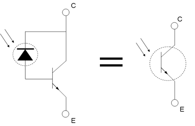


So, when the phototransistor receives the photons the output tries to go down to zero.

It acts like an inverter. Right?

I have a one more doubt i.e. what is the difference between photodiode and phototransistor?

What modification should I do for using photodiode in the circuit?
 

Photo_comparison.png


http://hades.mech.northwestern.edu/index.php/Photodiodes_and_Phototransistors

**broken link removed**
 

what is the purpose or R1?
 

To limit the current flowing in to the LED to a safe value.
 

Status
Not open for further replies.

Similar threads

Part and Inventory Search

Welcome to EDABoard.com

Sponsor

Back
Top