Continue to Site
Follow along with the video below to see how to install our site as a web app on your home screen.
Note: This feature may not be available in some browsers.
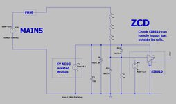
...thanks, so you mean use an INAMP instead of a diff-amp?The inputs have not identical input impedance, thus you get bad common mode rejection ratio.
There is no connetion between AC input and your circuit GND, thus they float with respect to each other....thanks, so you mean use an INAMP instead of a diff-amp?
Do you think there will be big common mode noise, and it will end up ruining the zero cross signal?
The "amplifier" actually attenuates by some 100x, rather than amplifying, as you will know.
assuming i read your schematic correctly, you have the inverting input of the op amp
1 diode drop from 5V and 1 diode drop from ground (BAT54 in both cases)
what am i missing?
according to digi-key, BAT 54 is obsolete