Continue to Site

Welcome to EDAboard.com

Welcome to our site! EDAboard.com is an international Electronics Discussion Forum focused on EDA software, circuits, schematics, books, theory, papers, asic, pld, 8051, DSP, Network, RF, Analog Design, PCB, Service Manuals... and a whole lot more! To participate you need to register. Registration is free. Click here to register now.

Precise RF envelope detector for 70MHz

Status
Not open for further replies.

mtwieg

Advanced Member level 6
Joined
Jan 20, 2011
Messages
3,835
Helped
1,310
Reputation
2,626
Reaction score
1,405
Trophy points
1,393
Activity points
29,370
As a small part of a larger project, I have to recover the amplitude of a narrowband 70MHz signal (bandwidth is maybe 10KHz max). The signal's amplitude ranges from 0-50mVrms. We're looking for a relatively simple, fully analog solution. The tough part of this is that we want to detect the signal's amplitude all the way to zero with minimal nonlinearity (like within 1dB). Preamplifying the signal before detection is fine. Also we want an output voltage proportional to input amplitude, not dB (which is what the single chip solutions seem to give...).

We've so far tried diode detectors using a few different diodes on hand (BAT54 seems to work better than others, but we're not sure what is suitable for this), and we've been putting a DC bias on the signal before the diode in order to try and improve sensitivity at the low signal range. This, along with about 32dB of preamplification, gets us pretty far, but we still lose sensitivity at input levels around 5mV and below.

I do not have a good reference frequency to work with, so doing a downconversion to baseband isn't going to be possible. We've floated the idea of splitting the signal, feeding it into both a comparator to create a clock, and then mixing that with the small signal version, thereby making a product detector (I think?), but I suspect we'll have issues with unpredictable phase shift between these two paths, making the measurement unreliable. Another idea I had would be to have a rough local oscillator close to the signal frequency (say 69MHz), mix that with the 70MHz signal to get a 1MHz IF, then using precision rectifier circuits with op amps to get a good, linear envelope out of that.

Do any of those methods sound reasonable? Are there any quick tips for getting the simple biased diode detector to work better? I've come across some concepts that seem useful (hot carrier diodes, zero bias schottky detectors), but I'm not sure if they really address our problems. It would be nice to have something simple like that work well.

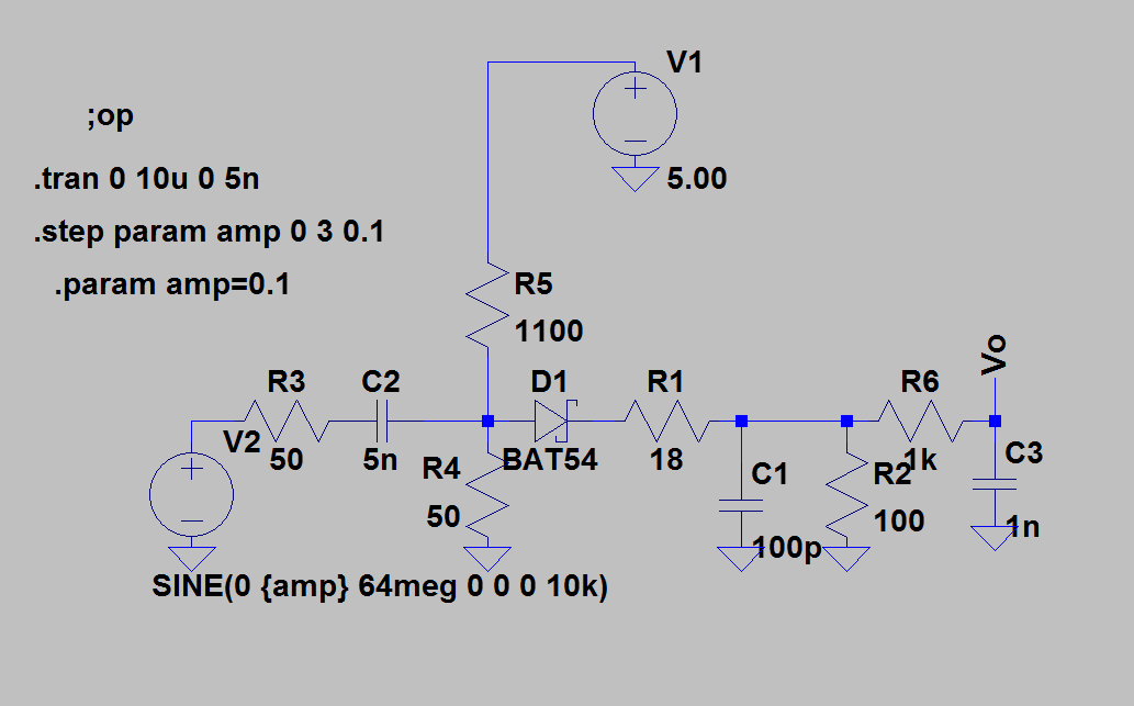
Attached is a schematic of the detector circuit we've been playing with until now, not showing the preamplifiers. Here the diode is biased so there's about 15mV of signal on the output with no input, so the diode is biased with about 150uA. It still loses sensitivity at low input levels though:
 

By nature, a self-steered demodulator can't be linear down to zero signal level. In so far the discussion can be only about optimizing the detector response, linearizing the characteristic and compensating temperature drifts. I also guess, that a biased schottky diode will give best results, and that a high speed, low capacitance and low voltage diode should be preferred.

Zero bias detector designs are used to extend the quadratic characteristic range maximally, which obviously isn't your intention. The respective "zero bias" diodes may be suitable anyway. You should also consider, that the simple SPICE models shipped e.g. with LTSPICE give only a rough estimation of real diode behaviour, it's better to rely on own measurements.
 
  • Like
Reactions: mtwieg

    mtwieg

    Points: 2
    Helpful Answer Positive Rating
try a log detector chip or rms detector chip
I've done a search for these and all of them seem to be very nonlinear (as in they don't follow any kind of simple trend) or they accurately have a linear in dB output, which we don't want.
 

You can't avoid to do some linearization at low levels, so using a detector with a clearly defined non-linear characteristic may be actually an alternative. I assumed however, that (thermal) rms detectors won't give sufficient sensitivity. The thermal detector point reminds me to the fact, that you didn't specify a response time respectively detector bandwidth. Also the accuracy requirements are yet unsaid.
 
  • Like
Reactions: mtwieg

    mtwieg

    Points: 2
    Helpful Answer Positive Rating
By nature, a self-steered demodulator can't be linear down to zero signal level.
Why, because of issues with creating the high amplitude LO from the signal? We already have a circuit which recovers the zero crossings of the signal and gives a good square wave down to pretty low signal amplitudes.
I also guess, that a biased schottky diode will give best results, and that a high speed, low capacitance and low voltage diode should be preferred.
So far I've tried a BAT54 (best so far), a BAV99 (which was much worse), and a 1n4148 (a bit worse than the BAT54), and I can't see any trend in diode type or properties vs performance. The fact that the BAV99 performed worse than the others really threw me off, since its datasheet claims it has the fastest recovery time, and the lowest capacitance.
Zero bias detector designs are used to extend the quadratic characteristic range maximally, which obviously isn't your intention. The respective "zero bias" diodes may be suitable anyway.
To clarify, I think there are two things that I've seen called "zero bias" detectors. One is what I'm doing, where you take a normal diode and put a DC bias across it to improve linearity. Then I've seen another technique in which a diode is used without an external bias, but the diode is tailored in a way that allows it to be sensitive anyways. I believe it's due to a higher reverse saturation current, thus giving it a lower impedance at zero bias. Is this the technique you're referring to? Do you think It would be useful to me? I've seen it referenced mostly in RFID tags where no external bias is available.
You should also consider, that the simple SPICE models shipped e.g. with LTSPICE give only a rough estimation of real diode behaviour, it's better to rely on own measurements.
Right, I mainly made that simulation to play around with and see if I could replicate my measurements. Also to have something to post as an example.

---------- Post added at 11:14 ---------- Previous post was at 11:11 ----------

You can't avoid to do some linearization at low levels, so using a detector with a clearly defined non-linear characteristic may be actually an alternative. I assumed however, that (thermal) rms detectors won't give sufficient sensitivity. The thermal detector point reminds me to the fact, that you didn't specify a response time respectively detector bandwidth. Also the accuracy requirements are yet unsaid.
Well the response time should be defined by the signal bandwidth, which is about 10KHz (maybe less). I'd say a time constant of 50us would be fine. +/-0.5dB of error within 200us sounds good. We're flexible.

For accuracy, we'd be fine with +/-0.5dB of error over the full range, with a dynamic range of 30dB.
 

Why, because of issues with creating the high amplitude LO from the signal? We already have a circuit which recovers the zero crossings of the signal and gives a good square wave down to pretty low signal amplitudes.
A technique with carrier recovery and a mixer would be the opposite to "self-steered" demodulation in my view. If you want to go for any kind of synchronous demodulation and are worried about phase errors, than the "big solution" involving quadrature demodulation and possibly a PLL to adjust the phase would help. (The method is also called "lock-in amplifier" in some application areas).

I'm not surprized, that the schotky diode BAT54 performs better than standard pn diode 1N4148 or BAV99 (which is almost the same chip). But BAT54 is a 200 mA diode with rather large area, I would assume better performance with dedicated detector diodes.

I'm not aware of the term "zero bias" detector being used for circuits with bias. But it's clear, that an unbiased diode will have a non-linear (typically quadratic, linear in power) characteristic, as shown below for a BAT62 schottky detector. The optimization point with dedicated zero bias detector is mainly to achieve a frequency independent response and a wide quadratic range, but also other diodes will show a similar behaviour.

 
  • Like
Reactions: mtwieg

    mtwieg

    Points: 2
    Helpful Answer Positive Rating
A technique with carrier recovery and a mixer would be the opposite to "self-steered" demodulation in my view. If you want to go for any kind of synchronous demodulation and are worried about phase errors, than the "big solution" involving quadrature demodulation and possibly a PLL to adjust the phase would help. (The method is also called "lock-in amplifier" in some application areas).
We don't have access to the carrier unless we recover it from the AM modulated signal. I'm not sure if mixing with the recovered carrier really qualifies as "synchronous" or not. But I thought that using it in a homodyne converter would be good enough. Phase shift would cause the detected amplitude to be reduced, but so long as it's still linear vs input amplitude we probably don't care, so I don't think we would need both I and Q outputs.
I'm not surprized, that the schotky diode BAT54 performs better than standard pn diode 1N4148 or BAV99 (which is almost the same chip). But BAT54 is a 200 mA diode with rather large area, I would assume better performance with dedicated detector diodes.
What are special about "detector" diodes? I've seen a few from avago that are specified for detectors, but nothing in their electrical characteristics really stands out.
I'm not aware of the term "zero bias" detector being used for circuits with bias.
I think it's misuse of the term that I picked up somehow... but I still think it's useful for improving linearity.
But it's clear, that an unbiased diode will have a non-linear (typically quadratic, linear in power) characteristic, as shown below for a BAT62 schottky detector. The optimization point with dedicated zero bias detector is mainly to achieve a frequency independent response and a wide quadratic range, but also other diodes will show a similar behaviour.

That diode has unique specs and that plot shows about as much range as we're looking for. If it turns out we do need a better detector then I'll definitely give that a try, thanks.
 

That diode has unique specs and that plot shows about as much range as we're looking for. If it turns out we do need a better detector then I'll definitely give that a try, thanks.
It's a typical "zero bias" detector diode I think. But what I wanted to show is the quadratic slope of the characteristic. It's not giving a voltage linear output as you intend it without applying a squareroot function.
 

Are you sure? It looks linear on the plot, at least the ones with high RL, with Vin<100mV. Hard to see a parabolic curve on a log-log plot.
 

Ah, okay, didn't realize a square law function would be linear on a log log plot, but I guess it just doubles the slope. I'm not observing such a response with my setup, though. Possibly because of the biasing, and the fact that our input signal is much larger (like 100mV min, after the preamplifiers). Are detector circuits normally operated in that small quadratic range? If biased, can the upper linear range extend down to small input voltages?
 

Status
Not open for further replies.

Part and Inventory Search

Welcome to EDABoard.com

Sponsor

Back
Top