Continue to Site

Welcome to EDAboard.com

Welcome to our site! EDAboard.com is an international Electronics Discussion Forum focused on EDA software, circuits, schematics, books, theory, papers, asic, pld, 8051, DSP, Network, RF, Analog Design, PCB, Service Manuals... and a whole lot more! To participate you need to register. Registration is free. Click here to register now.

Precise Low-Cost AC Zero-Crossing Detector

Status
Not open for further replies.

KerimF

Advanced Member level 5
Joined
May 17, 2011
Messages
1,556
Helped
376
Reputation
760
Reaction score
379
Trophy points
1,373
Location
Aleppo city - Syria
Activity points
13,106
Hi,

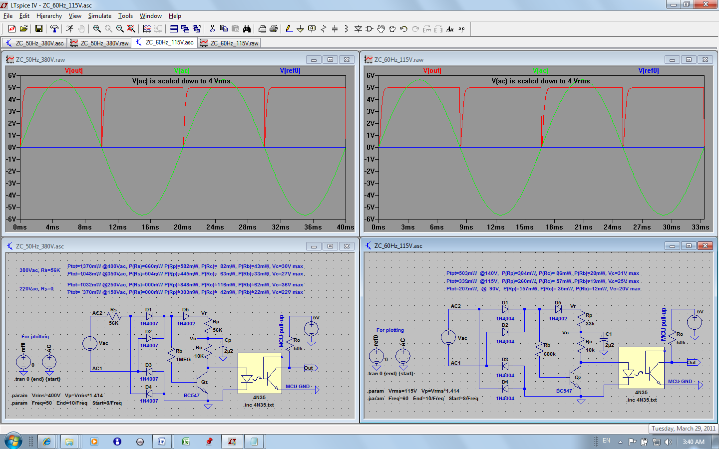
Those who use to work with triacs and thyristors may like to know about my AC zero-crossing detector (I already uploaded versions of it in the files section of Electronics_101 and LTspice groups).
As you will see, it differs from the already known equivalent solutions as follows:

(1) Its falling edge is within 100us (typically less) in all possible conditions (voltage, temperature and component characteristics... etc).
(2) Its total power dissipation is relatively low up to 400Vac (in comparison to known direct detectors).
(3) low cost standard components (as optocoupler 4N35).

I attached two versions; one for 60Hz and another for 50Hz.

Please feel free to comment or ask for any further details.

Kerim

 
Last edited:

That's cool, but what's wrong with just using a bidirectional input optocoupler directly of the mains?
 

That's cool, but what's wrong with just using a bidirectional input optocoupler directly of the mains?

It seems I missed a good AC detector while searching for one.

I hope the new one will:

be more precise when the mains voltage varies,
or
dissipate less power on 400Vac,
or
cost less.

I appreciate knowing more of what you have in mind. Perhaps it will be a better solution in respect to any of the above 3 points. Thank you in advance.

Kerim
 

Well I guess if you really want delay of 100us or less, then you'll need some active amplification of the signal. I don't think a bidirectional coupler could meet that spec. Yours seems to work fine, but it looks like it would be susceptible to stray capacitance. Like try putting a few nF across the output of your full bridge and it will probably stop working.
 

Well I guess if you really want delay of 100us or less, then you'll need some active amplification of the signal. I don't think a bidirectional coupler could meet that spec. Yours seems to work fine, but it looks like it would be susceptible to stray capacitance. Like try putting a few nF across the output of your full bridge and it will probably stop working.

You gave indeed a good point.
Although the controllers based on this detector work fine, it won't hurt me to analyse more in depth the effect of this stray capacitance and its worst case value. Thank you.

Added:
As a simple modification for a better performance is to add a 470K resistor between the base and the emitter of the transistor Qz (this works well for C_stray<100p).
And if for a reason the stray capacitance after the bridge can reach the value of 1n, another resistor (220K) should be added at the bridge output.
Practically the first modification will likely be enough since the actual controllers work fine without it so far (but I have just noticed that this the first time, since long, I forgot to place a resistor between the base and the emitter!).
 
Last edited:

Real grid has quite a bit of noise that will prematurely trip a zero crossing solely based on level without any filtering. With noise filtering you need to take into account delay due to filter, which usually means a one shot multivibrator, slightly shortened in AC period to generator the zero crossing trigger at the next zero crossing point.
 

Real grid has quite a bit of noise that will prematurely trip a zero crossing solely based on level without any filtering. With noise filtering you need to take into account delay due to filter, which usually means a one shot multivibrator, slightly shortened in AC period to generator the zero crossing trigger at the next zero crossing point.

In my case and for our industrial local grid, I took into consideration this possible noise while writing the firmware of the controller MCU:

First, the first valid falling edge is latched and the interrupt routine is disabled till before the arrival of the following expected valid one (with reasonable margin).

Second, a temporary system halt occurs if the zero-crossing timing becomes outside the margin limits. In the costly controllers, I enable an internal synchronized trigger for a reasonable number of mains cycles during severe low frequency interferences (the effect of high frequency noise is minimal for this detector and its controller) .
 

Stray capacitance on the base of the BJT shouldn't be so much of an issue, but capacitance in the bridge is. Putting a resistor in parallel should help a lot though. And seriously who really cares if you draw a few extra mA from a 400VAC line...
 

Status
Not open for further replies.

Similar threads

Part and Inventory Search

Welcome to EDABoard.com

Sponsor

Back
Top