Continue to Site

Welcome to EDAboard.com

Welcome to our site! EDAboard.com is an international Electronics Discussion Forum focused on EDA software, circuits, schematics, books, theory, papers, asic, pld, 8051, DSP, Network, RF, Analog Design, PCB, Service Manuals... and a whole lot more! To participate you need to register. Registration is free. Click here to register now.

Precise Full Wave Rectifier at high frequency

Status
Not open for further replies.

uday mehta

Advanced Member level 4
Joined
Dec 30, 2011
Messages
104
Helped
6
Reputation
12
Reaction score
6
Trophy points
1,298
Activity points
1,979
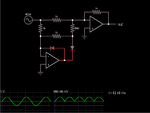
I designed a Precise Full Wave Rectifier using op-amp. but there are some problems i am facing at high frequency
i) at high frequency i got some -ve voltage(may be due to reverse recovery time i don't know).
ii) positive pulse of it's o/p is amplitude dependent. i.e. at 200 mv i got o/p of positive pulse is less then 200 mv but at 2 volt i got o/p of positive pulse is more then 2 volt.
there is no problem with o/p of negative pulse.
I am using 10 Khz i/p frequency.
here is the circuit diagram.
I am using 10K in place of 1 K and 5 K in place of 500ohm.
 

Attachments

  • full-wave-rectifier-with-op-amps.png
    full-wave-rectifier-with-op-amps.png
    3.3 KB · Views: 424

What P/N? Vcc? Vee?
You need to look up if it is rail-rail out/in and if so what is max Iout since these types are ~5k output impedance so internal loss and supply headroom are important.
Otherwise scale R values even higher.
 

I hope you are not using a slow old LM324 quad opamp (or its sister the LM358 dual) that has trouble above 2kHz.
I also hope you are not using very slow mains rectifiers that work poorly above 1kHz.
 

200mV @ 10 kHz shouldn't be a problem with the standard rectifier circuit using moderate speed OPs and fast diodes. Problems arise if you go for higher frequency and considerably smaller input voltage. In this case, alternative precision rectifier circuits may be considered.
 

You cannot expect to use the inverting input of a PFWR cct. without a Vee supply below the input negative peak, as this design uses the negative peaks and then inverts them again.

Therefore either add bias then cancel it or add a negative supply.

IF you are using an appropriate Vee negative supply but the output fails to drive enough current to bias the diodes then you MUST CONSIDER the Zout of CMOS being up to 10k and choose R loads of 100k,50k or higher

Note I used 20k,10k here with 10k ZOut and it had no error when I bypassed the simulation of internal resistance with 4Vpp in and +/-5V supply.
PFWB.jpgbut showed obvious error before when switch was open. (allow java to run sim)
 
I am using mcp6022 op amp, diode is 1n4148. Vdd is +2.5 V, Vss is -2.5 V.
and input signal is varying. I am testing this circuit from 200 mv to 2 V.
 
Last edited:

Your opamps and diodes are fast enough for the circuit to be a very good precision active fullwave rectifier at 10kHz. But if the circuit is built on a solderless breadboard then the capacitance between the rows of contacts and jumper wires will ruin the response and perhaps cause oscillation. Since your supply is only plus and minus 2.5V then the circuit will not work properly if the input exceeds about 1.6V.
 
You cannot expect to use the inverting input of a PFWR cct. without a Vee supply below the input negative peak, as this design uses the negative peaks and then inverts them again.

Therefore either add bias then cancel it or add a negative supply.

IF you are using an appropriate Vee negative supply but the output fails to drive enough current to bias the diodes then you MUST CONSIDER the Zout of CMOS being up to 10k and choose R loads of 100k,50k or higher

Note I used 20k,10k here with 10k ZOut and it had no error when I bypassed the simulation of internal resistance with 4Vpp in and +/-5V supply.
View attachment 117696but showed obvious error before when switch was open. (allow java to run sim)
Your design should work up to Vcc-Vf for diode drop of 0.7!, thus (2.5-0.7) 1.8Vp max not 2.0V. Use Schottky diode if you need more headroom. Your design is clipping in the 1st stage!!!

Test it with a 100% AM signal as I have shown and show input and output signal and photo of layout with probes using very short wires.

MCP602x is perfect with R-R I/O and 100Ω output impedance (2.5V/25mA Vcc/Isc) far better than previous generations.
 
Status
Not open for further replies.

Part and Inventory Search

Welcome to EDABoard.com

Sponsor

Back
Top