Continue to Site

Welcome to EDAboard.com

Welcome to our site! EDAboard.com is an international Electronics Discussion Forum focused on EDA software, circuits, schematics, books, theory, papers, asic, pld, 8051, DSP, Network, RF, Analog Design, PCB, Service Manuals... and a whole lot more! To participate you need to register. Registration is free. Click here to register now.

Practical matching of complex input impedance of a dipole

Status
Not open for further replies.

usman_mahfooz

Member level 2
Joined
Aug 19, 2006
Messages
50
Helped
3
Reputation
8
Reaction score
2
Trophy points
1,288
Location
PAKISTAN
Activity points
1,583
Need Guidance
OK i have a dipole whose Zi changes due to close proximity of parasitic elements.
Complex input impedance is 150+160i .
And its surely complex (not 200 ohm ) due to parasitic effects :)
How can i achieve it practically.
Can Quarter Wave transformer be used in this case. if it can how can i use it somehow with a balun. I m using a 50 ohm coaxial.
Thanks in Advance
 

what's the operating frequency?
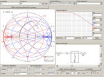
you can design a matching network for each arm of the dipole to convert the (150+160i)/2=75+80i to 25Ohm, then quarter wavelength balun can be connected after that matching newtwork?

below is an example(f=2.4G):
mn.jpg
 
If you already know the complex impedance of your dipole (or any device), use Smith diagram to find how to transform it into a matched line impedance. All basic RF textbooks have the method described in detail.
 
A standard method (but narrowband) is to add a length o 50 ohm transmission line to rotate your complex impedance so that the imaginary part goes to zero. At that point, read the real impedance and use your quarterwave transformer to match that.
 
Status
Not open for further replies.

Part and Inventory Search

Welcome to EDABoard.com

Sponsor

Back
Top