Continue to Site

Welcome to EDAboard.com

Welcome to our site! EDAboard.com is an international Electronics Discussion Forum focused on EDA software, circuits, schematics, books, theory, papers, asic, pld, 8051, DSP, Network, RF, Analog Design, PCB, Service Manuals... and a whole lot more! To participate you need to register. Registration is free. Click here to register now.

Power Supply Topology

Status
Not open for further replies.

VJKris

Member level 1
Joined
Jun 22, 2012
Messages
33
Helped
0
Reputation
0
Reaction score
0
Trophy points
1,286
Activity points
1,530
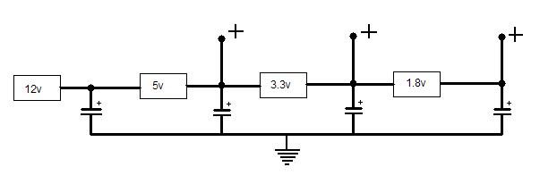
Is it advised to use the below power supply topology for a PCB design?
I have a input 12V supply and the board needs 5V(.5 A),3.3V(.4A),1.8V(2A) supplies.

12 V to 5 V (using Buck Regulator)

5V (Buck Regulator output ) to 1.8 V Buck Regulator/3.3 V LDO.{5 V to lower voltage conversion using switching regulators)


Is it advised to use the output from a buck regulator(5V) and use them to generate other lower voltages(using buck regulators)?
Will there be any issues w.r.to noise coupling or any other issues.Please advise.
 

Because of the low voltages, I would use synchronous buck converters. That are converters where another mosfet shorts the freewheel diode to reduce freewheel (catch) diode conduction loss.

When converting from 12V directly to 1.8V, you get short high current spikes at the 12V supply (as the switch current in a buck converter equals the output current). There can be an EMC advantage by feeding the 1.8V converter from the 5V converter, however, you may experience instability at the 5V output. This is because of the input of switch mode buck regulators shows negative resistance. So when using cascaded converters, check the behavior at all possible load situations.
 

The amount of power dissipated or wasted by the regulators id simply the potential difference between input and output multiplied by the amount of current flowing through the regulator. If you make sources from a 12 v to 5V(.5A), 3.3V(.4A), 1.8V(2A) supplies, the total current will be 0.5+0.4+2.0=2.9A.
I would advice to put buck regulators in series, one after another, to reduce the maximum power dissipation on a single regulator. Something like this....


To reduce noise, put some capacitors w.r.t ground... Noise can exist and if the sources are sensitive to any frequencies (for logical use) that noise have to be filter.
 

Dear VJKris
Hi
There are many ways available for you ! but i think a simple flyback or forward converter as a multi winding , can help you as well . but if you don't want to do it , i think you can use some LM2576 as a chain , too !
Best Wishes
Goldsmith
 

I would avoid cascading multiple SMPS for this, due to potential instability. A multiple output flyback could theoretically work, but in practice it would be pretty difficult to get an accurate 1.8V output.

I would just use three separate buck regulators, each fed by 12V. Synchronous rectification should be used on at least the 1.8V supply.
 

I would avoid cascading multiple SMPS for this, due to potential instability. A multiple output flyback could theoretically work, but in practice it would be pretty difficult to get an accurate 1.8V output.
Hi dear Mtwieg
I think if we design a flyback converter and then we use a simple regulator IC , for 1.8 volts it will be ok . isn't it ?
Best Regards
Goldsmith
 

Status
Not open for further replies.

Similar threads

Part and Inventory Search

Welcome to EDABoard.com

Sponsor

Back
Top