Continue to Site

Welcome to EDAboard.com

Welcome to our site! EDAboard.com is an international Electronics Discussion Forum focused on EDA software, circuits, schematics, books, theory, papers, asic, pld, 8051, DSP, Network, RF, Analog Design, PCB, Service Manuals... and a whole lot more! To participate you need to register. Registration is free. Click here to register now.

power supply to my old Skil 2972.

Status
Not open for further replies.

DeepOne

Advanced Member level 2
Joined
Feb 26, 2011
Messages
632
Helped
99
Reputation
200
Reaction score
100
Trophy points
28
Location
45N39E, Russia
Activity points
0
has spent whole evening on this ).


Last edited:

Need to ask questions:

1. Does it run when AC is connected?

2. How old is the battery pack? They only last a certain amount of time.

2. Do you know if the battery pack gets any charge?

3. Can you remove the batteries? Can you test what power they provide?

4. Does it run on AC with the batteries removed?

5. Did you circle the two components in the schematic? Zener diodes? Schottky diodes?
 

1. Does it run when AC is connected?
answer yes. Now it worked only if АС connected.

2. How old is the battery pack? They only last a certain amount of time.
this brand named "Skil" is glorified by low quality of battery pack. So battery has served around several months. Afterwards I soldering new battery. But most of time device worked from external 6V acid battery because internal 0,8Ah 7,2V battery so little .

3. Do you know if the battery pack gets any charge?
answer yes.

4. Can you remove the batteries? Can you test what power they provide?
answer yes.

5. Does it run on AC with the batteries removed?
This scheme is AC-DC converter, so no need batteries .


6. Did you circle the two components in the schematic? Zener diodes? Schottky diodes?
there signed in scheme. This is pack of 30A 50V shottky diodes, taken from old broken PC power supply.

Ferrite core is taken from faulty high frequency AC-AC 70W converter from 12V halogen lamps. Total price of components around 6$ ).

Power of the converter uncomplicated to enlarge for feeding any cordless tool
 
Last edited:

thanks for the kind words.
Then you also made the printed circuit board yourself?
Yes, but this does not deserve mentionings.

Also, it is necessary to provide reliable double insulation between winding of the transformer, since cordless tools is not calculated on work with power network.
 
Last edited:

My own apologies for lifting the old subject, but editing already impossible.

Here is else another version, with feeding ir2153 through Viper12 (or 22).
 

Attachments

  • 2153__diptrace2107.zip
    6.3 KB · Views: 135
Last edited:

Happy crhistmas for all peaple of forum...
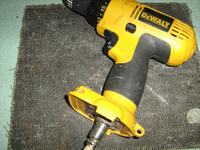
I have a drill cordless Bosch PSR 18VLi-2 new, but it not work because card module electronic system is broken and it is not repairable , the bosch technical assistance can replace only with a new module electronic board that has a price highest, halves the whole drill. I wanted to have here some idea and help from you of the forum that you are very prepared and experienced. The drill cordless is of European manufacture, therefore it should be fed with an adapter power supply 230 V home, the system elettrical of the drill works with 18 V battery lion. Someone of you has a project or address whether to find scheme circuits. The circuit, should work for 18 V, output and 230V 50 hz input.

I would have another question!! . does the drill have a system of check for overheating of the tool, did I want to know, how to by-pass this system, as do I owe wire connect the 4 pins under the drill ? and to make to work with an adapter trasformer the cordless drill?
I can to attach files and photo if you have need... Very thankful and happy to Visarei to discuss with you... The drill bosch is new and is sorry me to throw away.


I in advance thank
 

Happy crhistmas for all peaple of forum...
I have a drill cordless Bosch PSR 18VLi-2 new, but it not work because card module electronic system is broken and it is not repairable

The card must do several jobs. It must convert:

(1) incoming mains to DC volts

(2) charge the LION batteries without overcharging them

(3) supply power to the motor (probably as pulsed DC)

You will need to construct all the above functions, in order to replace the card.

A simple way to run the drill would be to connect the switch from the batteries to the motor. It would run at maximum speed.

I do not know what device there is (or needs to be) to prevent overheating. But one may be required.

You would need to provide the means to charge the batteries. There are guidelines for charging LION type, because they need care in how long and fast you charge them, or else bad things happen.
 

I can to attach files and photo if you have need...
Exactly, photographies of drill and battery entrails there be useful (please compress it for no more than 200kb sizes).
check for overheating of the tool, did I want to know, how to by-pass this system
It is necessary to think twice previously than by-passing battery protection systems. However if battery not used that not important.
 
Last edited:

hi... yes the motor power in DC, seeing the photos, you will understand that this drill has a board electronic too module complex and delicate. I have need to try to start the drill without battery, because I don't have it. I must power turn on the drill with 18V under the drill there are 4 pins for to connect battery slot, can I connect 18V to the pins only + and - and to leave the two central pins free?
 

Attachments

  • IMG_0060b.jpg
    IMG_0060b.jpg
    274.9 KB · Views: 187
  • IMG_0059b.jpg
    IMG_0059b.jpg
    143 KB · Views: 181
  • IMG_0058b.jpg
    IMG_0058b.jpg
    193.9 KB · Views: 171

Hi.
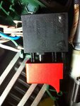
Similars in regulator button only sensors and possible contacts of the reverse, but power part is located on unserviceable card module with puttied by white microcircuit.
can I connect 18V to the pins only + and - and to leave the two central pins free?
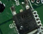
Unless imitate batteries presence on these central contacts that electronics most likely will not allow to work, particularly if take into account that card module electronic system is broken.
So the simplest way - change this electronics on selfmade pwm regulator. Or change button of the regulator on spare part from any inexpensive chinese cordless drill (possible gain for cost around 5 USD beside me). Then will possible use any external feeding.
 
Last edited:

Untitled 3b.jpgUntitled 4b.jpgIMG_0062b.jpgHappy Christmas ..
. I have made other photos in board circuit, and I have found a component that appears burn exploded, you see photo. in the photo "untitled8b.jpg? , a swollen explosion is seen, I believe it is broken. then I don't understand that component's type to be it. can you tell me you? in board pcb is written as Q1.

can you help to find me a trigger Chinese compatible switch? untitled62b.jpg

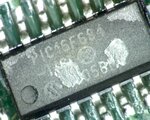
I have made enlargement zoom of the IC PIC that you have tell me, it is now seen in code IC PIC 16F684, rigth ?.

If I replace these two electronic components, does thing think of this?

I need to find the way to still work with this drill... Can you tell me which first step I must do? I could purchase these components, but I believe that IC Pic must be eproom programs.

Or to replace the trigger switch with a Chinese part?

thanks DeepOne

- - - Updated - - -
 

Attachments

  • IMG_0062b.jpg
    IMG_0062b.jpg
    184.3 KB · Views: 137
  • Untitled 4b.jpg
    Untitled 4b.jpg
    133.1 KB · Views: 171
  • Untitled 3b.jpg
    Untitled 3b.jpg
    143.6 KB · Views: 123

Happy Christmas, certainly.. but in Russia this holiday celebrate at January 7. However i`m not against if celebrate this holiday twice ).
in board pcb is written as Q1.
obviously this is inexpensive low voltage mosfet, like IRLU024 N or IRLR024N (N-MOS 55V. 17A (Logic-Level)) If this mosfet perforated on G-S line that probably carry away else PIC16 microcontroller. If this suggestion is correctly that possible only use this card module as scrap, since MCU without program is useless.
On the other hand if MCU is alive there is chance of repair for all device.
If I replace these two electronic components
Except this it is necessary to check condition of signal and power lines in accordance with this mosfet. Advisable also understand reason of this fet mortality.
can you help to find me a trigger Chinese compatible?
For this it is necessary simply to take this switch and ask spare parts seller to find similar from standpoint of the sizes. Certainly if You have such seller around.
which first step I must do?
I shall begin with define of trigger switch input wires. If there is direct output from internal changeable resistor (three fine white wires)?
If it is impossible to gain access to variable resistor output of trigger switch so better search for chinese analogue. If it is possible - better do PWM regulator - this is simply. So there is sense to open trigger switch and study its internal scheme.
Or really possible begin with mosfet changing. Its price approximately around 1USD so You do not lose nothing.
 
Last edited:

little improved version
 

Attachments

  • pcb.zip
    5.3 KB · Views: 133
Last edited:

this is really great, how long did you spent on it?
 

Hello; great work, i would like to know
if this circuit you designed would work with 120vac or
no?
also, where would i find the parts you used from over the counter equipment,etc?
i live in a place where we dont have electronic supplies(IC chips, diodes,etc)
thanks

naitek
has spent whole evening on this ).


Hello.
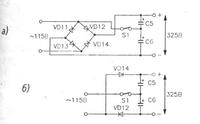
It is possible use this converter with 120V. For this it is necessary to use capacitive voltage doubler (like in PC PSU) or change parameters of the transformer (reduce number of whorls in primary winding) with enlarging capacity of half-bridge capacitor(s).
i live in a place where we dont have electronic supplies
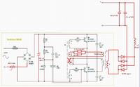
in such event possible to try to remake hf converter that for 12V lamps.
 
Last edited:

I am sorry, i dont completely understand.
I am new to this.
where would one put the capacitive voltage doubler ( location in pc psu)? or
how would i change the number of whorls in primary winding .

*other question. With the hf converter for 12v lamps( ballast lighting) , the issue is maintaining the proper amouont of
amps to sustain power to the drill,etc.
is there perhaps another place you know where i can see the 120v circuit already built?

thanks DeepOne.
 

capacitive voltage doubler:

how would i change the number of whorls in primary winding
whorls amount possible to calculate manually, or with help of some program intended for this, or it may be selected experimentally.
It depends basically from voltage, frequencies and core parameters.
is there perhaps another place you know where i can see the 120v circuit already built?
I don`t see this circuit for 120V but there not will too be a greater change from 220V circuit.
maintaining the proper amouont of amps to sustain power to the drill
250W lighting ballast must be sufficient in most cases.
I am new to this.
Probably better take the big iron transformer from unnecessary UPS and connect it with rectifier and output filtering chains. This will be simply, reliable and safely. But weighty )
 
Last edited:

Status
Not open for further replies.

Similar threads

Part and Inventory Search

Welcome to EDABoard.com

Sponsor

Back
Top