Continue to Site

Welcome to EDAboard.com

Welcome to our site! EDAboard.com is an international Electronics Discussion Forum focused on EDA software, circuits, schematics, books, theory, papers, asic, pld, 8051, DSP, Network, RF, Analog Design, PCB, Service Manuals... and a whole lot more! To participate you need to register. Registration is free. Click here to register now.

power supply questions

Status
Not open for further replies.
To calculate RMS involves finding the area under a curve, then leveling it out evenly across a cycle, to arrive at the equivalent level if it were constant.

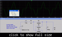
The green plot shows current coming from the transformer.

So with a little measuring, I find the area under a green burst can be spread out (over a timeframe of 8.3 milliseconds), so that the equivalent current is no more than 0.3 A on the scale at the right.

I'm ignoring the initial surge at the beginning of the time graph. That burst alone might have an RMS value of 584mA, but it's not what we'd call a running value.
 

Hi Brad,
I would have thought the same, but here is what I got when I told ltspice to start counting from 1.9 secs:

**broken link removed**

---------- Post added at 13:30 ---------- Previous post was at 13:30 ----------

the RMS reads 507mA
 

To my surprise, the RMS current through the generator is 585mA... almost twice as much as what I expected.
I just dropped in to the thread. The surprizing point for me is, that you got a lot of verbose explanations and suggestions, but nobody mentioned the simple fact, that the RMS input current will be considerably higher than the output current, and that it of course depends on the capacitor size.

I guess, that you are able to understand the effect by analyzing the input current waveform, applying the quadratic RMS calculation rule.

The simulation however doesn't exactly apply to a real transformer, because you have to consider it's ohmic (winding resistances) and reactive (leak inductance) output impedance. It will result in a lower RMS current but also a reduced output voltage. The unloaded output voltage of a small transformer is considerably higher than the assumed value. If designed correctly, it will supply the nominal voltage and current to a resistive load connected directly to the transformer.

For a 6V 1.9 VA transformer, I determined these parameters:
open circuit voltage 8.6V
output resistance 7.7 Ohm (uk,r = 40%)
output reactance 5.4 Ohm (uk,x = 28 %)
Using uk relative impedance voltage numbers, you can easily scale the parameters to a different transformer. If you know the values of larger transformers, you'll notice, that small transformers have a considerably higher impedance voltage, respectively voltage drop at nominal load.

P.S.: uk is actually the German formula symbol for impedance voltage or "Kurschlussspannung". The usual English symbols are Req and Xeq respectively.
 
Last edited:

Bradtherad , I say you are wrong, if you simply integrate the pulse area across the whole time scale you are just finding the mean current. RMS = the root of the mean of the SQUARES. So lets say you have a current pulse of 3A for a period, then two periods with no current. The currents/period = 3,0,0 . the currents squared/period are = 9,0,0 . the mean is 9/3 = 3A the root of this is 1.7A not 1A.
Frank
 

Fvm, thanks for clarifying with an explanation for the paradoxical reading.

Bradtherad , I say you are wrong, if you simply integrate the pulse area across the whole time scale you are just finding the mean current. RMS = the root of the mean of the SQUARES. So lets say you have a current pulse of 3A for a period, then two periods with no current. The currents/period = 3,0,0 . the currents squared/period are = 9,0,0 . the mean is 9/3 = 3A the root of this is 1.7A not 1A.

Thanks. Looks like I fell into the easy mistake to make.

I understand RMS was invented to yield correct readings for non-sine waveforms (whereas the typical averaging meter is calibrated for a sinewave). RMS also works correctly for non-symmetrical waveforms (which the typical averaging meter cannot handle).

And I understand RMS is the figure we'd arrive at by creating the identical heating effect across a resistor, as compared to the heating effect obtained with a sine wave. And I understand that RMS yields a figure about 11 percent higher for a sinewave than we get by using the averaging method.

If I owned an RMS voltmeter I would have experimented with it so as to get better acquainted with the idiosyncracies of RMS measurements. And I would have known better how to explain the anomalous value of 584 mA RMS as calculated by the simulation.
 

Interestingly, the RMS current is considerably smaller if you put in reasonable transformer impedances. The input current is also almost independant from the capacitor size, only the voltage ripple changes.


indeed interesting and question provoking ;)

1- how did you get those parameters? Do you have any books/websites to recommend?
2- what happens exactly if I try to draw too much current from a transformer?
3- is my understanding correct that if I need to draw 500mA RMS from a 9V transformer then it needs to be rated at least 4.5VA?

thanks!!
 

1- how did you get those parameters? Do you have any books/websites to recommend?
The impedance voltage numbers used in my simulation have been measured from a real transformer. You usually won't find them in datasheets. But you mostly get a specification for the open circuit voltage. You can either use an assumption for the Req/Xeq ratio, or derive Req from a measurement of primary and secondary windings resistance. For the relation of Req, Xeq, Zeq and output voltage drop, you have to refer to general AC network theory. Transformer equivalent circuits should be a least covered in electrical power engineering text books.

2- what happens exactly if I try to draw too much current from a transformer?
3- is my understanding correct that if I need to draw 500mA RMS from a 9V transformer then it needs to be rated at least 4.5VA?
Transformer rating is in fact the point, where RMS current matters, also fuse dimensioning and ripple current capability of capacitors. The resistive transformer losses are proportional to the RMS output current. According to my simulation results, the transformer has to be rated for at least 4 VA. But if you change the transformer, you have to put in the impedances and open circuit voltage for the new one.
 

Status
Not open for further replies.

Similar threads

Part and Inventory Search

Welcome to EDABoard.com

Sponsor

Back
Top