Zedman
Full Member level 6
Hi,
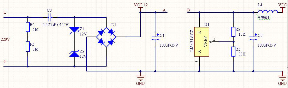
I got a PCB, it's a small remote controlled relay. It has this non isolated power supply part. As far as I figured it out it looks like the attached schematic, except it uses a transient suppressor instead of the two zeners.
But i cannot see the PCB lines under some parts (eg. the relay), so I couldn't figure out what is between point A and B.
From the TL431's datasheet there can be just a resistor which limits the current of the output and the current to sink when there's no load.
I built it with just a 220 ohm resistor between A and B.
At the point Vcc 12 there's 13.4V on the original PCB, and it gives 3.1V at Vcc.
Mine works the same way with small differences in the voltages, BUT when I attach the relay between the Vcc 12 and GND points the output voltage gets down to 1.6V causing the MCU to reboot.
I know due to the 0.47 uF cap it will only give max 30mA but on the original PCB the 3.1V remains 3.1V even if the relay is on!
(I am using the same 12V/400mW relay)
What could be between A and B points causing the stability of the output?
thanks,
Zedman