Tomas1707
Newbie level 6
Hi,
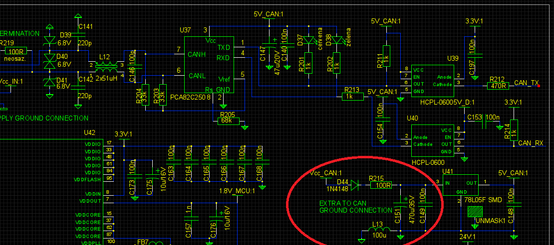
I have a question about power supply filtering. We have a HF system working on 8 MHz. It consists of transmitter and receiver. A couple of these devices have together power supply of 24 V. The devices are also connected with CAN bus for the communication with each other and to set parameters from the PC. We had encountered problem with receiver signal interfered by the transmitting on the CAN bus and discovered, that the cause of the interference is the power supply of the CAN transceiver, that ''pulls" the together 24 supply and also 24 V power supply for HF power amplifier on the transmitter pcb. We have solved this problem by "filtering" the input of the voltage regulator for the CAN tranceiver (see fig.) with 100 ohm resistor in series and 470 uF capacitor. Because the input voltage is 24 V and output voltage is 5V, there is enough reserve for the voltage drop on the 100 ohm resistor. Resistor limits the current from the 24V input supply when CAN transceiver transmitts on the bus and capacitor supplies the "missing" current, so there aren't current pulses on together 24 V power supply and on the 24 V supply on the transmitter pcb.
CAN speed is 125 kbps.
My question is, if there can be some problem with this solution?
The only thing I can think of is the warming up of the capacitor due to the ripple current and so the shortening of its lifetime and capacitance, but the transmitting is not so often, so the temperature shouldn't rise much.