Continue to Site

Welcome to EDAboard.com

Welcome to our site! EDAboard.com is an international Electronics Discussion Forum focused on EDA software, circuits, schematics, books, theory, papers, asic, pld, 8051, DSP, Network, RF, Analog Design, PCB, Service Manuals... and a whole lot more! To participate you need to register. Registration is free. Click here to register now.

Power Supply 9V, 3A current limiting

Status
Not open for further replies.

jonnybgood

Full Member level 4
Joined
Dec 28, 2010
Messages
214
Helped
3
Reputation
6
Reaction score
1
Trophy points
1,298
Activity points
3,011
Hi,
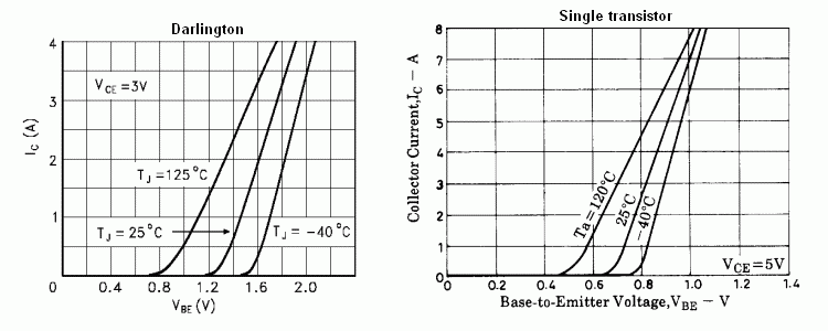
I have designed and sumulated the power supply attached with current limiting at 2.7A. First i tried using a power PNP for switching (bypassing current) and current limiting. My output voltage was dropping to 8.5 - 8.7V from 9V while current limiting circuit wasn't quite working as calculated. With the darlington BDX54 things are much smother with a dummy load of 3.33Ω which comes from 9V/2.7A current is 2.66A and 8.9V. Can someone explain the advantages of using larger resistors in current limit and bypass circuit. When I tried working with resistor values derived from the switching 0.7V I didn't have good results. Regarding the ripple voltage, is it a convention to set it to 5V when working out the smoothing capacitance

Cap = (I×t)/Vripple ?

Power supply.gif
 
Last edited by a moderator:

I can think of two possible reasons for the current limiting problem. The first one is your use of 0.7V as the threshold voltage. A transistor does not suddenly go into full conduction at a specific voltage like an ideal zener diode. It starts to conduct at a certain Vbe level and current increases rapidly with increasing voltage. The second reason is that the threshold voltage varies from transistor to transistor so that R3 has to be matched to the threshold voltage of Q2. The matter is further complicated by the fact that the threshold voltage also varies with temperature. Look at the curves in the diagram below and you'll see what I mean.

16_1323245952.png


As to the reason why your circuit works better with a darlington than with a single transistor, my guess is that the 0.4 ohm resistor happens to be better matched to Q2 than the resistor you chose for the single transistor. It may not work that way in an actual construction.

In practice, you will get more accurate current limiting if R3 is adjustable. Even then, it will be subject to temperature variations. To have more precise control, different design techniques will have to be used.
 
Thanks this helped me a lot. In your opinion what is the best alternative for steady voltage with the current limiting if more accuracy is needed. I need to stick with linear power supplies and I do not want to involve any microcontrollers.
 

Did you check accuracy of this circuit? What is the percentage of accuracy here and what accuracy you need?
 

Well the accuracy with the darlington pair is not so bad at least in the simulation. If I consider using op amps like with an LM317 so at least I would improve the output voltage accuracy. Will I be back to square one with the same current limiting method?
 

Current limiting method has nothing to do with the accuracy. Current limiting and accuracy are two different things. Current limiting is connected with the load circuit and is a safety like for the load circuit. If you use a simple (for understanding) 100µF capacitor as smoothing capacitor and then you use a semiconductor in circuit for current voltage control, the effect of smoothing capacitor is simply multiplied with 100 which means a 10µF capacitor will give you a 1000µF effect.
 

Current limiting method has nothing to do with the accuracy. Current limiting and accuracy are two different things. Current limiting is connected with the load circuit and is a safety like for the load circuit. If you use a simple (for understanding) 100µF capacitor as smoothing capacitor and then you use a semiconductor in circuit for current voltage control, the effect of smoothing capacitor is simply multiplied with 100 which means a 10µF capacitor will give you a 1000µF effect.

"the effect of smoothing capacitor is simply multiplied with 100" - are you referring to the Beta of the semiconductor?
 

Status
Not open for further replies.

Similar threads

Part and Inventory Search

Welcome to EDABoard.com

Sponsor

Back
Top