rfeyer
Newbie level 5
Hi All,
I am new to this forum and new to electronics (old in life, though") ) I started playing with components and schematics about 3 mo ago - please be gentle.
) I started playing with components and schematics about 3 mo ago - please be gentle.
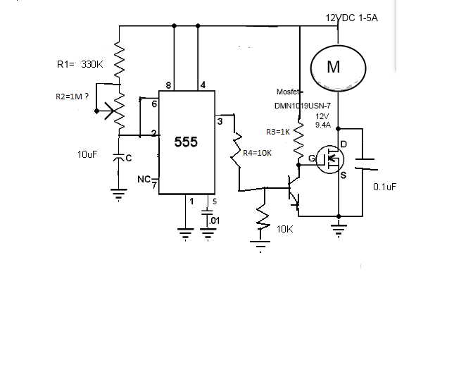
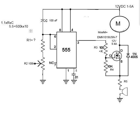
I have a 12vdc 5A source which will supply a 12VDC motor to open a small door.
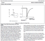
Then the source is opened (i.e.: the 12VDC) I would like the stream to be intercepted by a 555 timer and Mosfet, allowing a variable (by potentiometer?) 5 to 20 seconds to elapse, then allow current to continue to motor and CONTINUE until original 12VDC is turned off. If the below is anywhere close (partially copied from online and modified) then I would like to add a buzzer as well but will try to figure out placement and resistor values.
So, does it look like the below would do/ handle the task, and, if so, what potentiometer would I purchase?
And again - the current has to stay ON after the time delay
Thanks in advance
<a title="Door Delay.png" href="http://obrazki.elektroda.pl/5323796600_1425925436.png"><img src="http://obrazki.elektroda.pl/5323796600_1425925436_thumb.jpg" alt="Door Delay.png" /></a>
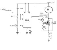
Not sure If I understood the picture linking procedure correctly, hope it worked
I am new to this forum and new to electronics (old in life, though
) I started playing with components and schematics about 3 mo ago - please be gentle.I have a 12vdc 5A source which will supply a 12VDC motor to open a small door.
Then the source is opened (i.e.: the 12VDC) I would like the stream to be intercepted by a 555 timer and Mosfet, allowing a variable (by potentiometer?) 5 to 20 seconds to elapse, then allow current to continue to motor and CONTINUE until original 12VDC is turned off. If the below is anywhere close (partially copied from online and modified) then I would like to add a buzzer as well but will try to figure out placement and resistor values.
So, does it look like the below would do/ handle the task, and, if so, what potentiometer would I purchase?
And again - the current has to stay ON after the time delay
Thanks in advance
<a title="Door Delay.png" href="http://obrazki.elektroda.pl/5323796600_1425925436.png"><img src="http://obrazki.elektroda.pl/5323796600_1425925436_thumb.jpg" alt="Door Delay.png" /></a>
Not sure If I understood the picture linking procedure correctly, hope it worked