cks3976
Full Member level 6
Dear All,
I want to implement a power switch using an power MOSFET. Specs are : Vin: 12VDC and IDS: 10A. Gate trigger shall be initated by a Microcontroller (3.3V).
I can think of following implementations:
Option 1: 12V source voltage will be connected to the Source of the P-channel MOSFET and the Voltage-out will be on the drain. Connect the microcontroller trigger to a Charge pump and use this to turn the power MOSFET On. VGS_threshold of the MOSFET is around 22V.
OR,
Option 2: 12V source voltage will be connected to the drain of an N-channel MOSFET, while grounding the source. Gate of the MOSFET will be directly driven by the microcontroller (3.3V/ 5V). During Gate current ON, the MOSFET will conduct and 12V will not be switched to the output stage. And when the gate current is OFF, the MOSFET is turned off and the output will get 12V (reverse logic).
Please help me in underststaning whether above logcs are correct, if not how can I implemet the switch for above specs.
Thanks a lot
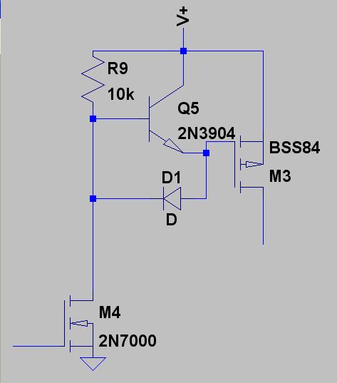
") Barry... thanks for nice explaination...however I was planning to use a limiting resistor on both drain and source. But since my load must be ground referenced, I cannot connect the two ends of load to 12V and drain point. Hence I use Option 1 and NPN transistor driver for Gate...
Barry... thanks for nice explaination...however I was planning to use a limiting resistor on both drain and source. But since my load must be ground referenced, I cannot connect the two ends of load to 12V and drain point. Hence I use Option 1 and NPN transistor driver for Gate...