cupoftea
Advanced Member level 5
Hi,
A customer has sent us an 150W isolated SMPS, which is "supposed to be" Power Factor corrected. Its a One Tran Forward, with large L leakage in the transformer, (instead of an output inductor). It has a high voltage reset cap (for resetting the transformer) which is kept below 500V by a regenerative SMPS snubber, which bleeds the reset cap down so it stays below 500V. (just shovels the energy into the primary DC Bus)
It has a 5u6 Film cap after the mains rectifier bridge.........we dont have a harmonics tester, but do you confirm with us that there is no way that this thing can pass mains harmonics to EN61000-3-2 , class D with that size of capcaitor after the bridge?
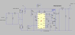
Just so we know what i am talking about...the attached is a Flyback PFC in LTspice and jpeg....changing C7 to 5u6 (it should be around 330n) shows how poor the mains harmonics become with this size of cap ...i know its a different topology, but the principle is the same,.
A customer has sent us an 150W isolated SMPS, which is "supposed to be" Power Factor corrected. Its a One Tran Forward, with large L leakage in the transformer, (instead of an output inductor). It has a high voltage reset cap (for resetting the transformer) which is kept below 500V by a regenerative SMPS snubber, which bleeds the reset cap down so it stays below 500V. (just shovels the energy into the primary DC Bus)
It has a 5u6 Film cap after the mains rectifier bridge.........we dont have a harmonics tester, but do you confirm with us that there is no way that this thing can pass mains harmonics to EN61000-3-2 , class D with that size of capcaitor after the bridge?
Just so we know what i am talking about...the attached is a Flyback PFC in LTspice and jpeg....changing C7 to 5u6 (it should be around 330n) shows how poor the mains harmonics become with this size of cap ...i know its a different topology, but the principle is the same,.
Attachments
Last edited: