wfg42438
Member level 3
- Joined
- Jun 29, 2015
- Messages
- 54
- Helped
- 0
- Reputation
- 0
- Reaction score
- 0
- Trophy points
- 6
- Location
- California
- Activity points
- 620
Hello,
At the moment i have an assignment dealing with a SCR switch
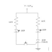
We are asked to build and simulate the circuit shown below. Unfortunately we have not covered the material needed in class at the moment. So i figured id ask around to get a head start on this assignment.
From my understanding the SCR switch acts as a controlled diode. The gate terminal when excited allows current flow and when the anode has a voltage more negative than the one across the cathode then the SCR turns off. The SCR will only begin to conduct until it is once again excited by some specific gate current.
Now unfortunately that's all i know based on some internet searches i conducted. However its not enough to get started.
For this exercise we need the following:
Need to calculate the gate current I_G and what is being referred to as current I_A
Im assuming I_A is the DC current that splits between the two 1k resistors current
Can someone please give me some pointers on where to start??
Also there's a component shown in the bottom center of the circuit diagram is this a switch? If so what kind?
If someone can also point out why V_supply=-7V that would be great!
Thank you in advance!!!
At the moment i have an assignment dealing with a SCR switch
We are asked to build and simulate the circuit shown below. Unfortunately we have not covered the material needed in class at the moment. So i figured id ask around to get a head start on this assignment.
From my understanding the SCR switch acts as a controlled diode. The gate terminal when excited allows current flow and when the anode has a voltage more negative than the one across the cathode then the SCR turns off. The SCR will only begin to conduct until it is once again excited by some specific gate current.
Now unfortunately that's all i know based on some internet searches i conducted. However its not enough to get started.
For this exercise we need the following:
Need to calculate the gate current I_G and what is being referred to as current I_A
Im assuming I_A is the DC current that splits between the two 1k resistors current
Can someone please give me some pointers on where to start??
Also there's a component shown in the bottom center of the circuit diagram is this a switch? If so what kind?
If someone can also point out why V_supply=-7V that would be great!
Thank you in advance!!!
