B
BlackMamba
Guest
Project by piotrekp90
Source Modu
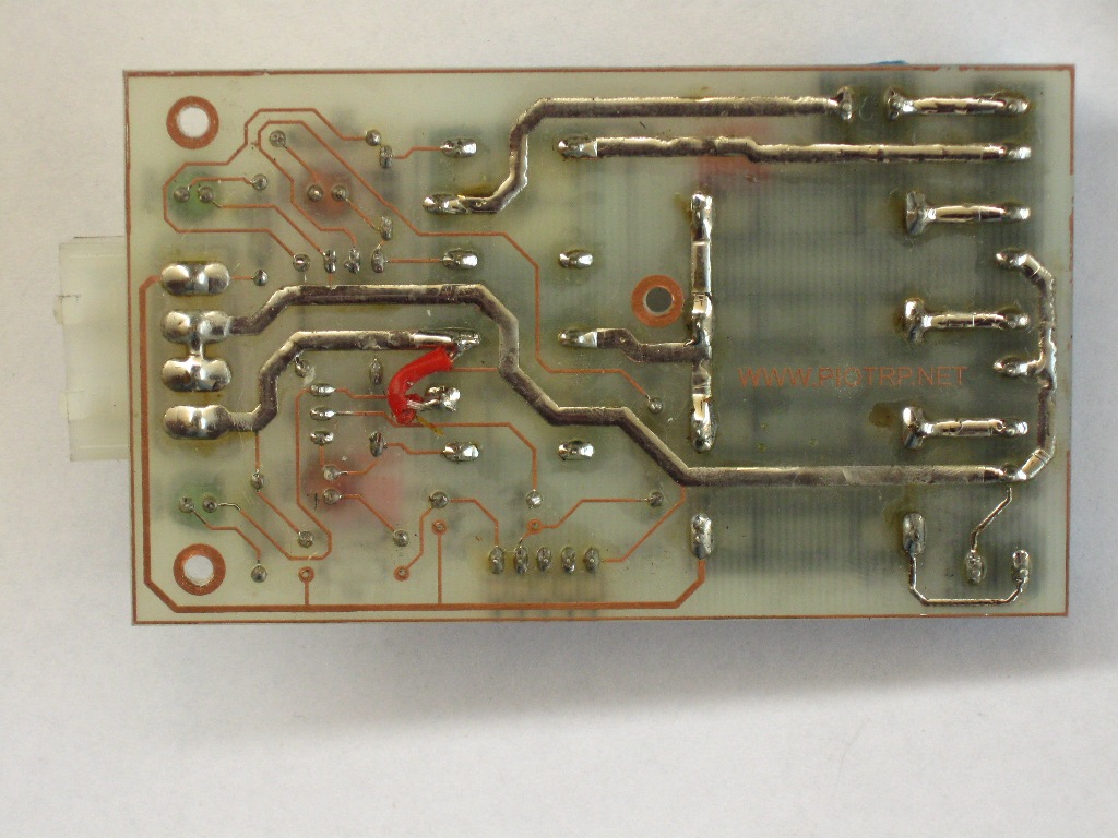
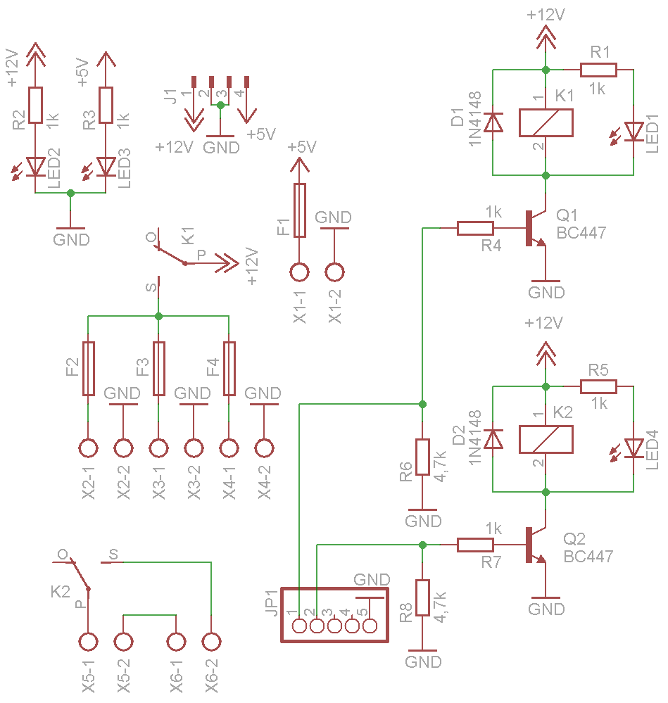
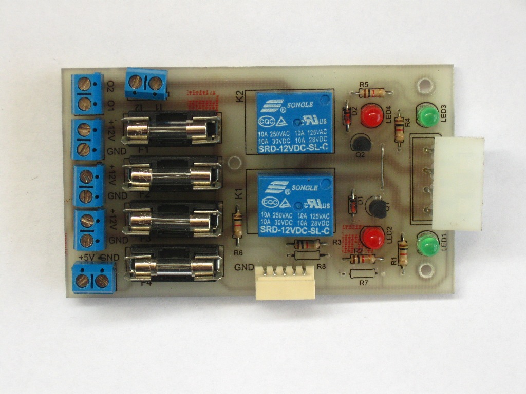
The module distributing Power is presented. Separate anti-shorting fuses for each circuit are built in. Module is adopted to distribute power from PC PSU.
It is very simple module consisted of a few elements. Resistors R2 and R3 deliver proper current for diodes LED2 and LED5. These LEDs indicate presence of +12V and +5V. Resistors R1 and R5 protects LED1 and LED4 against excessive current. LED1 and LED4 indicates state of relays K1 and K2. Diodes D1 and D2 protects transistors against overvoltage generated during switching off coil of relay. Resistors R4 and R7 fix maximal Q1 and Q2 transistors base current. Resistor R4 and R6 connects bases of these transistors to the ground. Fuses F1, F2, F3 and F4 protect particular power lines.
K1 relay connects the power to sockets X2, X3 and X4. K2 relay connects X5-1 and X6-2 pins, so we can connect here devices working on different voltage than distributed by module.
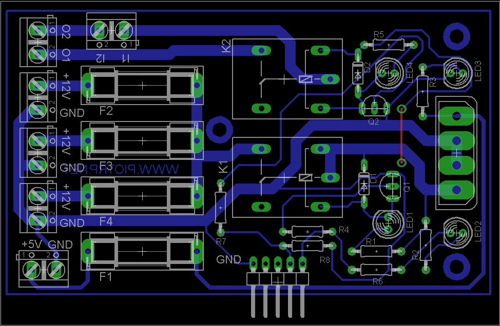
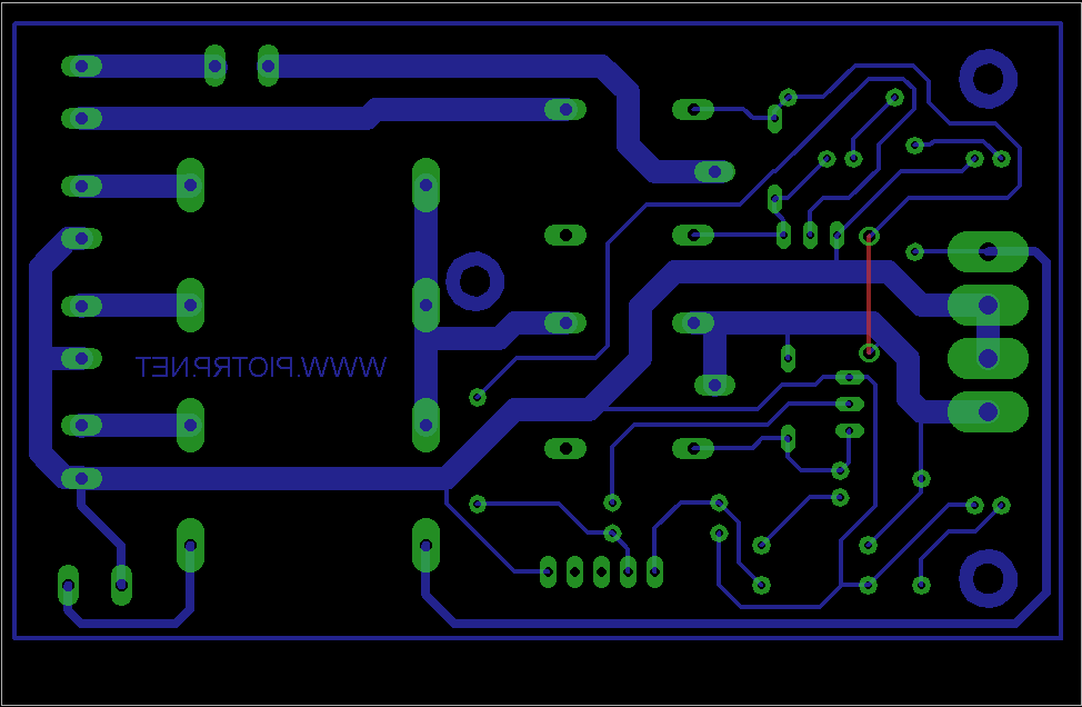
On **broken link removed** there is schematics of device and pcb layout for downloading.